Required tools & equipment’s:
- Drill Machine
- Jig Saw Machine
- Hilti machine
- Tool Box Set
- Silicone Gun
- Ladder (Foldable)
- Clamp meter
- Manifold Gauge
- Flairing tool set
- Spanner set
- Copper pipe Bender
Installation Of Cold Storage Room
Site Preparation
Before commencing the panel installation the following works are required to be carried out.
- Check floor surface for leveled smooth finish concrete.
- Check the work area is clean and safe.
- Ensure all panels and equipment is suitably protected in store.
- Marking the location of the cold rooms.
Mark off the location of the room on the floor from one side. For Cold room, the floor insulation can also be realized by using floor panels that are directly installed on the floor surface before installing the wall panels. The final finish of the floor would be as per the client’s requirement & will be provided by contractor with necessary identification.
Floor angles are fitted on the base floor to the required dimensions of the cold rooms.
Generally 100 x 75mm floor angle fabricated with the same sheet as that of the panel cladding material will be fixed to the floor by Hilti nail, to the required dimensions of the cold rooms.
Wall panels are installed on the fixed floor angles.
- Erect the first panel on the floor angle, start from one end.
- Apply an even thin layer of sealing compound on the joining face of the panels.
- Join the corner panel with wall panel by capping external and aluminium angle internal.
- Make sure that the proper side is up and fix another wall panel with the previously fitted wall panel by cam locks. Continue this process till the whole wall is finished.
- Apply sealing compound in the joining face of the panels.
Ceiling panels are installed to rest on the top edges of the wall panels.
- Apply an even thin layer of sealing compound on the outer plate seam of the ceiling panels, which is to be positioned on the farthest end of one side of the ceiling or on the corresponding part of the wall panel.
- Position the panel on top of the wall panels and suspension rods & top hat.
- Please refer to detail drawings.
- Proceed with the next panel and apply the sealing compound in the same way as before, against the wall panels as well as against the ceiling panel, earlier mounted. Join together by cam locks.
- Continue this process till all the ceiling panels are installed.
- Apply a string of white sealing compound in the joint between walls and ceiling panels and spread it. This will give an invisible junction between wall and ceiling panels.
- Silicon Sealants are filled at the joints of panels to ensure leak proof wall, ceiling surface.
Door Installation:
- Insulated doors (Self Closing Hinged Door with 1.0m high SS kick plates) as per the approved drawing is fitted in the cut out of the wall panel and located as per requirement and storage opening convenience. Then check the lock functions.
- Check that the sweeper type gasket under the door sweeps the floor at the time of operation, thereby arresting any ingression of outside air.
- PVC curtain to be hang from the top of the door to avoid air infiltration.
Fixing of lights.
- First marking to be done for lights in the ceiling.
- Light has to be fixed in the marking by nylon threaded rod & nut for bigger fittings and riveted with clamps for smaller fittings.
Fixing of Pressure Release Valves.
- Pressure Release valves are installed on the wall panels above the door openings in order to equalize the pressures of the room and the ambient condition.
- Pipe insulations can be cladded with foster cloth.
- Power Consumption = 11 kw, 3phase, 50 htz, 380 to 400 volts.
INSTALLATION PROCEDURE FOR REFRIGERATION SYSTEM:
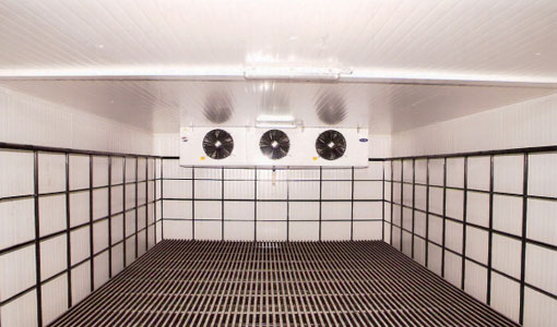
- Evaporator is installed as per approved drawing inside the chiller room at the ceiling level to ensure uniform, air-circulation.
- Condensing units for all cooling are installed as per approved drawing on the steel structure outside the cold room.
- The units are interconnected with copper pipes for suction, liquid and discharge line layout with necessary bends and fixtures.
- Evaporator and condensing units are inter-connected as shown in the basic refrigeration system diagram with necessary electrical wiring including the controls.
- Evaporator condensate will be connected to the nearest drain point.
- From the heat exchanger liquid line is connected to expansion valves through solenoid valve and suction line is connected to evaporator outlet.
- Filter dryer’s sight glass, shut off valve fixed on the foundation of condensing unit placed on GI frame and connected to the refrigeration circuit.
- After the completion of piping work, flush the system with nitrogen gas and allow passing nitrogen gas for checking the leakage of the system.
- Vacuum the entire system for 24 hrs by vacuum pump and then fill the system with approved refrigerant.
- The electrical control panel & display unit will be fixed in the cold room at desired height and location suitable for easy operation as per approved drawing.
- The control panel is designed for easy auto operation till the required temperature is obtained and it set to the temp differential ‘20 C’ so the system will maintain the required temperature.
- Finally units are commissioned and checked to obtain the required temp in the cold room. To prevent floor cracks during initial commissioning, the room temperatures to be reduced in 30 C
- For Refrigeration system designed with air cooled condensing units. All the other fixtures remain the same.
Discover more from Project Management 123
Subscribe to get the latest posts to your email.