This method statement covers the nature and type of work for water supply piping system Pipes & Fittings installation and Testing as per site requirements for any kind of the project.
All documentary requirements for this plumbing procedure will be submitted for approval and this will include Manufacturers data, certificate of compliance, brand designation, type and class including samples.
Below is necessary tools and equipment for the installation of water supply pipes and fittings.
- Lifting equipment’s
- Hand tools used for cutting the Pipes
- Standard mechanical Tool Box
- Measuring Equipment
- Sprit Levels
- Hand Gloves
- Hand pump & Pressure Gauge for Pressure Test
- Socket Fusion Machine for jointing of pipes
Roles and Responsibilities
Project manager have full authority and overall responsibility to manage, supervise, control the domestic water supply piping works and have direct responsibility for ensuring safe working practices and compliance with regulatory authorities’ requirements, co-ordinate with engineers and main contractor for execution of the works. Implement the project quality systems as per the satisfaction of the project requirements. Review changes and Variations to evaluate impact of those on time and schedule.
Project mechanical engineer is responsible for ensuring that all plumbing works are carried out as per the specifications, approved shop drawings and Method Statement as per the manufacturer instructions and coordinated with other MEP and civil works.
QA/QC engineer is responsible for monitoring and ensuring that the works are done in fulfillment with the specified requirements, and that all quality records related to the works are complete. Ensure that all installations are done as per approved material, approved layout shop drawing and coordination drawings, approved installation details, and approved mock-up. Carry out all the inspections with the site engineers and consulting engineers.
Site engineer shall co-ordinate all the site activities according to work schedule, and ensure the installation is done according to the Project Specifications, Manufacturer Data Sheet and approved shop drawings. Liaise with site representatives of client and consultants and coordinate safety procedures with site supervisors and site foremen. Will Co-ordinate and explain the routine work to the supervisors / site foreman. Ensure the compliance of works with the related approved Quality Control Procedure and co-ordinate with project engineer to advise for the areas to be issued for inspection.
The project team of experienced Supervisors and Foremen will ensure the quality of the installation work carried out, and will also ensure that it is as per the latest approved shop drawing issued for installation and according to instructions received from the Site Engineer.
Provide their subordinates (charge hand and skilled labors) adequate information to carry out their duties.
Ensure that he has adequate resources of machinery, labor and materials to carry out all the activities efficiently and to discuss with the Site Engineer.
Ensure safe and clean working environment to enforce a safe working habit.
The implementation of the procedures mentioned in method statement will be carried out by site Supervisor.
Pre Installation Requirements
All workers shall attend safety induction conducted by main contractor and specific training on the safe installation methods shall be given.
Task lighting to be ensured prior to start of Water Supply System installation in shafts.
Riser checklists to be filled and kept updated till completion of shaft installation.
Make sure the availability of approved shop drawing and all requirements of utility company where applicable.
Plan the installation shall be straight with fewer joints as possible.

Use standard fittings for all changes in directions and change in size, shape and connection.
Always make sure that water supply piping installation shall be vertical or horizontal to structural elements to avoid diagonal runs.
The Site Engineer and Site Supervisor will give necessary instructions to tradesmen (Pipe fitter) and provide necessary approved construction/shop Drawings of latest revision along with coordinated layouts.
Site Supervisor/Foremen will also check that proper tools and equipment are available to carry out the work and are in compliance with contract specification.
The Site Supervisor also explains to the tradesmen regarding safety precautions to be observed during the water supply piping installation.
Prior to commencement of work, the Engineers & Supervisor/Foreman will inspect and ensure that all materials delivered to work place are checked / approved and shall ensure they are the relevant piece for the site and materials are not damaged, without excessive scratches or visible corrosion.
Shaft Preparation for Water Supply Piping
In shaft / riser works are carried out over temporary working platforms which are installed at every floor level.
Separate safety / emergency rescue plans and procedures are prepared.
Site supervisor/ safety supervisor shall check proper lighting and ventilation availability before starting any works.
Ladders / scaffoldings to be secured firmly over the working platform and checked by competent Safety Officer, prior to start of work.
Site supervisors to keep close check of working technicians in risers after regular intervals.
Prior to Hydro-Pressure Testing for Water Supply System Pipes and Fittings, “Pressure Test Permit” to be submitted and approved.
Sequence of Work for Water Supply Installation
Ensure the appropriate sleeves are fixed, on walls where pipe routing passes through, as per approved shop drawings and specification, during the construction of structural elements.
Install sleeves and fire sealing/ inducement collars/pipe wraps or other suitable means to maintain the integrity of fire rated walls/partitions when services penetrate at height (wherever required).
PIPING SUPPORTS
Water Supply pipes and fittings will be installed as per the approved layout with proper supports and without any deflection.
Provide anchors and guides on vertical and horizontal piping as and where to prevent undue stress on branches as indicated on approved shop drawings.
Make sure the pipes rest freely on supports, aligned properly before final connection/jointing.
SOFFIT MOUNTED PIPING
Move Scaffold into the position and check that all wheels are locked and outrigger stabilizers are extended to correct position. Only Scaffold that has been duly inspected, certified and tagged “safe/green” shall be used.
Check the dimensions to the finished face of the wall /soffit and / or column; report immediately any discrepancy to civil engineer.
Mark out vertical support threaded rod, channel position from grid lines, as per reference markings provided by surveyor.
Locations will be based on the approved shop drawings.
Check the correct elevation of support brackets from the datum provided by surveyor, do not assume that floor is always at correct finished floor level FFL.
Secure first section of vertical supports to the soffit as per the shop drawing details.
When sufficient number of support brackets is fixed, the pipes may be lifted into the position and secured to the bracket.
Clean thoroughly the pipes, so that all dust/debris is removed.
Lift the pipes, to the platform using lifts or chain blocks.
Fit the bracket support to the pipe.
Note: this operation may be carried at platform level and the prefabricated assembly lifted into the place.
Check the tightness of all the bolts.
Adjacent length of pipes shall be jointed using the methods below as per the corresponding type of pipes.
Select and install proper fittings for the change of direction or elevation of piping as per the approved shop drawings.
Allowance for movement due to expansion and contraction shall be made by change in direction of pipework, loops or expansion joints.
Branch connections to mains shall be made so as to avoid undue stress due to expansion and/or contraction.
At no time are tools and loose materials to be placed on or inside the pipes.
WALL MOUNTED PIPING INSTALLATION
Move scaffold tower into position and check that all wheels are locked and out rigger stabilizers are extended to correct position.
Mark out centre line of brackets position, check the centre line is plumb, if using cast- in channel, check that channel is plumb.
Mark out elevation of brackets using datum provided by surveyor. Do not assume that floor is always at correct FFL.
Fit the support brackets as shown in approved drawing details. Check tightness of all bolts.
When sufficient numbers of support brackets are fixed, the pipes/assembly may be lifted into positions and secured to the brackets.
Provide additional support at branch connections, changes of direction and when required as per site conditions. Branch connections, at any case, will not be supported by the pipe main.
Select and install proper fittings for the change of direction or elevation of piping as per the approved shop drawings.
Open ends of pipes at all stages shall be sealed to prevent ingress of any foreign materials.
INSTALLATION OF RISER PIPES IN SHAFTS
Adequate lighting will be provided and preparatory steps to be followed as mentioned above in this method statement.
Riser pipes will be lifted using chain blocks, nylon ropes and/or enough manpower depending on the weight of pipes.
In case chain blocks will be used, it will be installed in high level by means of C/channels bolted to base slab using anchor bolts. Hook chain will be wrapped around the channel and locked.
Pipes to be lifted will be supported by nylon ropes secured on the chain block, ensuring the safety of workers, structure and material.
Install the pipes as per type and method stated in this document.
Jointing of pipes is mentioned below.
PPR PIPES JOINTING METHOD
PPR Pipes will be joined by means of electro-fusion (thermal) welding tool.
Manufacturer recommended socket fusion machine to be used for joint of PPR pipes and fittings.
Check the temperature range of socket fusion heating tool is in between 260°C to 280°C.
Qualification certificate for PPR pipe welding personnel shall be provided for approval.
CUTTING: Cut the pipes down to required length, at 90° to the axis, using appropriate cutting tools.
CLEANING: Before welding, clean the pipes and fittings to remove dust, grease, etc. and make sure both are dry.
MARKING: Mark the required depth of pipe insertion into the fitting. For a given outer pipe diameter, see table below.
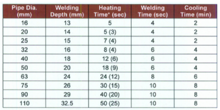

NOTES:
• Values presented in the above table refer to PN 16, PN 20 pipes and stabilized pipes.
• Heating time values in brackets refer to PN 10 pipes.
• With the outside temperature below +5° C, the heating time should be increased by 50%.
• Welding operation will be performed by qualified personnel only.
STRIPPING (stabilized pipes only): Before welding any stabilized PP pipes, remove a layer of aluminum with the outer plastic coating along the entire depth of the weld. To remove the aluminum coat, use a special coarse file with the diameter that fits pipe dimensions.
HEATING:
Simultaneously insert the pipe end and slide the fitting over corresponding heating tips of the welder.
Make sure the welder is heated up to 260°C to 280°C earlier.
Keep the required heating time, refer to table above.
WELDING:
After heating, remove both elements from heating tips and push the pipe into the fitting flange up to the depth marked earlier.
The welding time depends on the outside diameter of the pipe.
Good welds should have a double, uniform fin of material (fusion seam) pushed out to the surface, along the circumference of the connected elements.
All pipework and fittings will be installed and joint formed strictly in accordance with the pipe manufacturer instructions.
INSTALLATION OF UV STERILIZING UNITS
Ultra-Violet Sterilizing Unit will be installed comprising a housing with built-in UV lamps and a UV sensor to monitor the transmission of UV light.
Sterilizing unit shall have doped quartz glass to prevent the formation of ozone and nitrate.
The flow path shall be such that there are no radiation shadows.
Install the Ultra-Violet Sterilizing Unit with control panel featuring Start/Stop button, UV lamp fault indication, and UV intensity indication (%).
Install the unit in the location as specified in the approved layout drawings.
Make sure orientation is according to direction of flow.
Ensure the Ultra-Violet Sterilizing Unit is plumb and level.
Provide isolation valves on the inlet and outlet pipes. Also provide bypass valves for flushing and chlorination of water supply piping system and for future maintenance or repairs.
Install the fully-automatic backwash/self cleaning filter on the upstream end of the UV Sterilizing Unit.
Make sure Start/Stop push button is available on the control panel.
Connect the drain pipes to the nearest floor drain as per manufacturer recommendation.
SANITARY FIXTURES/FITTINGS INSTALLATION METHOD
Check all drawings to be used are in approved status. Use hand trolley in shifting of approved materials to site as per site conditions.
Identify and mark location of items to be installed. Install the sanitary fixtures/fittings as per manufacturer recommendation.
Fix all sanitary fixtures/fittings using screens, bolts etc.
Ensure that pipe fittings, offsets and connections are kept to a minimum.
Securely fix all fixtures/fittings to the structure and ensure they are plumb and level.
Make sure the fixtures/fittings and their plumbing connections will not be subject to any strain or load from the sanitary wares.
Ensure all fixtures/fittings are installed true, straight or where curved as per manufacturers recommendations to produce smooth, fair, and continuous radius.
Make sure that the concealed fittings are accessible for maintenance without affecting the structure or finishes.
Ensure that the fixtures and fittings are protected during construction.
Make sure that the final cleaning is done and all fixtures and fittings are put in working order on completion of construction.
Install trap before plumbing fixtures/fittings as recommended by manufacturer unless otherwise indicated on the shop drawings.
TRAPS INSTALLATION:
Jointing of traps to waste outlets is by use of supplied washer; do not over tighten the nut.
No other jointing compound or materials should be used.
Traps are available with either push fit or compression outlets.
Make sure all traps are provided with a means of access where required.
VALVES AND OTHER LINE EQUIPMENT INSTALLATION
Valves will be installed and connected where indicated in construction drawings and as per manufacturer recommendation in-line with flow direction.
Ensure pipe work is clipped securely in place and to specification.
After end of each work day, close all open ends with end caps to keep pipes clean from concrete pouring, dust and other construction debris.
AIR VENTING:
Provide air bottles and manual air release cocks at high points on all closed circuits and as indicated on the approved Shop Drawings.
Also provide an isolating valve on the system connection to the air bottle.
A 15 mm copper discharge pipe from the air bottle shall be carried to one meter above floor level and terminated with a lock shield isolating gate valve fitted with a screwed plug.
Install Automatic Air Vents at high points as per approved shop drawing, specifications and wherever required, in order to prevent and release any trapped air from the pipework.
Where automatic air vents are provided they shall be isolated from the system with a lock shield gate valve.
Make sure the air bottles and air vents have a discharge pipe connection to the nearest floor drain as indicated on the approved Shop Drawings.
Connect isolation valves as per the approved drawing.
Raise Request for Inspection of Installation of Water Supply Pipes and fittings including supports / brackets as per the approved shop drawing.
After installation has been approved, make sure to plug all connections / branches / drains and fill with clean water for hydro testing.
HYDROTESTING OF WATER SUPPLY SYSTEM PIPES & FITTINGS
Fill the whole water supply piping system with clean water.
Clean water for hydro-pressure test will be provided by main contractor/client from a temporary water supply tank.
The entire pipe work shall be hydrostatically pressure tested at 22.5 bar pressure as per specification and shall be recorded in the test certificate.
Water pressure test will be applied to the system in its entirety or in sections depending on the site conditions.
Make sure all open endings in the piping system to be tested are tightly closed with plugs.
Fill the system with water to the point of overflow from the highest point.
Momentarily open some plugs to make sure that all air has been vented and water has reached in all parts of the system.
When hydraulic test is to be carried out for an installation of multiple floors, pressure gauge shall also be provided at the highest point of the circuit.
Ensure test pressure is recorded at highest point of the system.
Pressure gauges will be identified with serial numbers matching the submitted copies of calibration certificates.
Keep the water in the system or in the portion under test for at least 15 minutes before inspection starts.
While the system is under pressure, make a careful inspection on all the pipes and joints.
If any leaks in the joints or defective pipe or fittings are revealed, stop the test, the defective pipe/ fitting shall be immediately replaced with new joints and materials.
After the correction is made and satisfactory conditions are achieved, the above test shall be re-started. Duration of test shall be 2 hours.
Raise Request for Inspection of hydro-pressure testing to consultant for witnessing and approval.
After approval of inspection of hydro testing, release the water gradually and completely, protect the piping installation and cap the ends of the pipe system.
Once the complete Water Supply Piping System is tested and approved, proceed with flushing and cleaning. (Method Statement for Flushing & Chlorination of Water Supply Piping System will be submitted separately).
After successful flushing and cleaning of pipework in accordance with specification/BSRIA, provide insulation as per the provisions of the minimum thickness tables for ‘Domestic Hot Water Supply (HWS) Installations’.
HWS pipework and fittings where concealed shall be insulated in accordance with the above mentioned provision of specification.
Proper identification labeling will be provided for all Water Supply pipe works as per specification.
Health and Safety Requirements
A task based risk assessment and mitigation strategy is prepared for this activity.
Work will commence as per safety regulations laid down in the contract specification and project safety plan.
Safety gears will be used. All personal protective equipment will be used as appropriate according to the nature of the job.
ELCB will be used in temporary panel boards; industrial connectors/sockets to be for temporary power cable connections.
Always maintain cleanliness in work areas. Housekeeping will be of good standard and all cut pieces and debris will be removed by the end of workday.
Ensure that all lifting operations are carried out as per approved procedures and safety regulations.
All scaffoldings will be checked by competent person and should carry green tags “safe to use”, prior to use for working purpose.
All plant tools tackles will have valid certificate. Lifting machines, appliances and gear to be examined by qualified rigger and come with valid certification.
Operatives working at height to wear their full body harness and should be anchored to a rigid point.
Nobody is allowed to stand on the top of the step ladder; worker should stand two rungs below from top of the step ladder. A co-worker must hold the step ladder while in use.
Work inside shafts are not allowed without work permit and supervision. Work areas to be provided with proper lighting and ventilation at all times.
Store tools and equipment and unused materials stacked in a safe area at the end of the workday.
Method statement / risk assessments to be briefed to all concerned personnel and signed as read / understood.
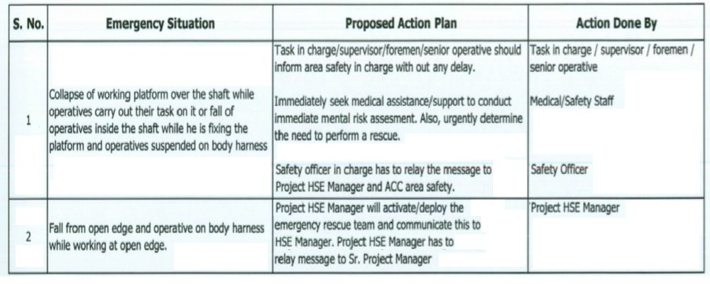
EMERGENCY RESCUE PLAN
This rescue plan has been compiled in order to comply with site safety requirements and for those who are working near open edges and over the shaft or during the installation of platform over the shaft.
This is to be brought to the notice of those exposed to the risk of working at height and those supervising and managing the same work at height.
In order to tackle any kind of emergency situation this requires immediate rescue of the personnel.
In case of any emergency rescue situation each crew plays their roles as detailed by using the first aid kit placed at project site and by coordinating with Main Contractor.
Contractor will arrange adequate personnel for the training in “Rescue from Height” from Safety Specialists. The names and training details will be provided upon receipt of the certificate after completion of training.
Rollgliss Rescue Kit R250 will be provided on site. This kit is designed for the rescue of a worker left suspended at height after a fall. It consist of the following:
1. R250 Descender: Aluminum
2. Rope: 11 mm nylon, minimum tensile strength 22.2kN
3. Extension pole: (telescopic) Aluminum, 1.2m to 5.0m
4. Anchorage strap: Polyester, 25mm width 5. Weight: 9kg (approximately)
6. Capacity: Evacuation and rescue of a person maximum weight 150kg
7. Compatibility: Rollgliss R250 is designed for use with DBI-SALA approved components or systems
8. Standards: ANSI Z1l7.1, EN 341, EN 1496 9. Country of Origin: France