

This method statement explains and covers the installation & inspection of cast resin Transformers but can be useful for other types of transformers.
The electrical standard procedure can be used for any kind of construction project covering the electrical scope of work.
Overall project manager is responsible for implementation of method statement and relevant forms and checklists in coordination with project team of engineers i.e. quality, safety and site engineers including supervisors.
Tools & Equipment’s
Arrange following tools and equipment before starting the work of transformer installation:
- Fork Lift or Crane, pallet mover with capacity & arrangement in line with the Manufacturer’s recommendations and as required at site.
- Portable hand tools/ Tool box / Power Tools
- Portable Drilling Machine/ Grinding Machine & Angle Cutter
- Spirit Level
- Level Threads
- Digital multimeter
- Earth resistance tester
- Measuring tape and setting out markers
- Welding Arrangement if needed
- PPE for all staff and labor
References & Standards
Project specifications – General Requirements of Electrical Services – Transformers
Approved material submittals
Relevant approved shop drawings
Approved coordination drawings
Project construction schedule
Project QA/QC Procedures PQP
Project HSE procedures (Health and Safety Plan)
Health and Safety Precautions
Ensure adequate PPE is available for all personnel.
Make sure that only trained and competent personnel are involved in transformer installation activities.
Ensure work area is free from debris and all access/egress are obstruction free.
Check and ensure that the lifting equipment/gear suitable for lifting and moving the transformers.
All the lifting equipment shall be certified and having valid certificates / test reports etc.
Warning signs and indication shall be displayed in working area.
Safety signs indicating all the hazards involved shall be displayed as necessary.
Extreme caution shall be exercised in handling materials and equipment’s in case of bad weather.
Quality Control Requirements
The equipment shall be inspected and checked against the relevant general arrangement drawings and approved material submittal.
Transformer shall be checked for any physical damage which may occur probably during the transportation/lifting.
The transformer shall be stored in sheltered, clean and dry ambient temperature.
Characteristics of the Transformer detailed on the rating plate shall be checked to those of the shipping documents and with those of the test reports attached to the transformer.
Each transformer shall be checked for the accessories, rating, name plate details, protection devices, indicators & terminal boxes.
Compliance of comments raised during factory inspection shall be checked.
The presence of all identifying and warning levels shall be checked.
An inspection request shall be raised for consultant approval upon receipt of the transformer and accessories at site.
Sequence of Work for Transformer Installation
All material required at installation site shall be inspected, handled and stored properly.
Any discrepancies, damage etc., shall be notified and reported for corrective action.
Material found not suitable as per approved material submittal shall be removed from site.
Proper storage shall be provided as per manufacturer recommendation.
Where auxiliaries are shipped loose, these will be identified and checked against the dispatch documents. Any item found missing or damaged will be noted to the supplier immediately for the replacement / repair.
Special attention shall be paid to the condition of instruments and monitoring devices supplied loose or installed along with the transformer.
Weight of Transformer shall be checked and suitable boom lifting crane shall be used for placing of the transformer in its final location through existing opening / passage.
Ensure all civil works are completed for the area including floor paint to carryout the installation, and clearance is obtained from respective authorities to proceed further.
Prior to start the transformer installation, refer to the approved shop drawings related to the area of installation and ensure that required materials are available at site as per approved material submittals.
Ensure the materials are stored properly and there is no mark of damage or deformity of any kind before issuing the material from site store.
Transformer will be off loaded to the place nearest to the installation and protected properly from dust & environment, etc.
Installation Steps for Transformers
Prior to installation, the foundation will be checked for cleanliness and level.
The unit will be inspected prior to shifting to site for any mechanical and structural damage during transportation.
Name plate will be checked against equipment data sheet to confirm conformity with the approval.
Ensure the installation of Transformers are carried out in accordance with manufacturer’s and local authority’s installation recommendations, requirement of applicable standards and in accordance with recognized industrial practices and specified in project specification to ensure that installation complies with requirements.
The area to be verified for the civil work that it has been completed and transformer installation work can commence.
Check area is clean for the positioning of lifting crane and transformers (as per approved sketch).
Extra precaution to be taken before lifting transformer, only manufacturers’ recommended special lifting eyes shall be used.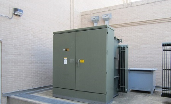

For lifting, the upper frame of the transformer lifting eyes for slings shall be used.
Transformer shall be lifted with maximum sling angle of 60 degree as per manufacturer’s recommendation.
If the transformer is complete with protection enclosure, roof shall be taken off to attach the slings.
Points of attachment shall be checked for cracked welds or loose nuts and bolts before lifting the transformer.
Guide ropes shall be used to prevent twisting or swinging of the transformer once it has been lifted clear of the ground.
Do not attempt to lift the transformers in high winds.
Transformer shall be placed down on the level surface capable of supporting its weight.
First stage, transformer shall be placed as per shown location by suitable mobile crane.
Second stage, transformer shall be placed on removable GI U channel at base level through existing opening by tower crane.
For locating the transformer in the final location, suitable lever on the special points foreseen on the lower frames shall be used to act only and not on the magnetic core and/ or on the windings.
Transformer shall not be moved by pushing the coils and the connections.
Transformer will be moved by crane using lifting lugs as per manufacturer’s, recommendation and shall be positioned on Transformer base in plant yard. Transformer will be moved over rails and brought to the position as indicated in the drawing, after installation of wheels at base.
The installation will be checked by site electrical supervisor and engineer for proper placement and orientation of Transformer.
After final positioning of transformer, all wheels will be locked to arrest any movements of the transformer.
Transformer auxiliaries and instruments will be installed as per manufacturer’s recommendation / guidance with close supervision of site Electrical supervisor and Engineer.
HV and LV side termination shall be carried out as per approved drawings.
Transformer Earthing shall be done as per local authority regulations, specifications and approved drawings.
After inspection of Transformer and approval by local authority and Consultants, proper care will be taken to protect the unit from dust by suitable covering, and shall further be released for the Testing work.
After placing and fixing the transformer at its final location, cable supports, cabling and terminations shall be completed as per approved drawings and manufacturer’s recommendation.
Installation of transformer shall be offered for client/consultant inspection and approval.
Attachments:
Approved Drawings
ITP & Checklists
Lifting Plan
Risk Assessment
Quality Control Procedure