General Requirements:
Formwork shall be so constructed that it will support the loads imposed on it by fresh concrete together with additional stresses imposed by vibrating equipment and by construction traffic.
For the construction of structural floor slabs formwork shall be used as per shop drawings and manufacturer’s recommendations. The PD 8 Shoring Tower & cuplock system will be erected on a load bearing horizontal base. The assembly of the shoring tower will be made horizontally and a crane is necessary for erecting.
PERI FORMWORK SYSTEM:
Base Area and First Level:
- Place two frames R150 on the supporting timbers.
- Wind the quick jack nut on the spindle, bolt the base plate with pins and cotter pins onto the spindle, and push the four base spindles into the bottom side of the vertical tubes of the frames.
- Insert two base spindles with a reinforcing support into the frame tubes.
- Push the second frame onto the base spindles.
- Insert frame connectors into top of each of the vertical frame tubes and secure it with pins and cotter pins.
- Stiffen the frames with diagonal braces.
- Wind out the spindles to the same height and secure it with spindle safety strap.
- Thus first level is finished.
Second level and Further Levels:
- For second level and further levels frames R150 and/or R110 can be used to adjust to the height.
- Fix the frame connector to the frames.
- Insert the frames at right angles to the lower level.
- Secure it with pins and cotter pins.
- Stiffen frames with diagonal braces.
- Repeat the same procedure for the desired height.
- Top Area:
- The top spindle will be a Cross Head Spindle.
- Wind the Quick jack Nut on the spindle.
- Push the Cross head spindle into the frame tubes.
- Wind the cross head spindle to the required height.
- Secure it with spindle safety strap.
- Thus the top area is finished.
- Now stiffen the shoring tower horizontally with a diagonal brace and raise with the help of the crane.
PERI SLAB PROPS:
PEP 20, PEP 30 slab props made of steel with high load bearing capacity and low weight shall be used for third floor slab and on wards. All the manufacturer’s details and instructions shall be followed for erection and dismantling /striking of formwork.
- Cross head or Claw head shall be mounted on the top prop and locked in place with the self locking coupling.
- The Cross headed props shall be secured with tripod (assembly aid) on a flat, clean and sufficiently load bearing surface.
- Cross head props shall be leveled.
- Main beams / Primary Girders shall be installed from below with the erection bar.
- The cross head securely supports one or two Main beams / girders with no risk of tipping.
- Cross beam / secondary girders shall be fitted from below with the erection bar.
- Secondary girders / Cross beams shall be adjusted so that plywood formlining joints are always positioned on a cross beam or pair of girders.
- Secure cross beams against tipping.
- Plywood shall be fitted and secure with nails.
- Intermediate props (if required) shall be provided with claw heads on the main beams.
CUP LOCK FORMWORK SYSTEM:
The statutory regulations and codes of practices detail common sense requirements and scaffolds shall be constructed in accordance with BS EN 12810-1:2003 & BS EN 12811-2:2003 codes of practice.
- Materials will be stocked within our storage area and will be used as per the site requirements.
- Materials will be set out in the relevant working areas by AJB operatives.
Procedure for Erection of scaffolding:
The erection procedure will be such that at no time is an unstable or unsafe scaffold left standing. All scaffolders will be working to SG4 standard ( Minimum 3 Boards, Single Guardrail & harness clipped to scaffold when working in an exposed area)
- All scaffolds should be erected on solid ground; sole boards will be used if the ground is soft. Base plates or adjustable base jacks must be used.
- The Cuplock system scaffold will be used for Access works whereby vertical standards are joined together by horizontal ledgers and fixed by means of a locking cup.
- The base lift will be erected first and then followed by a secondary lift, generally at a height of 2m. Bracing of both façade and ledger provides stability by using galvanized scaffold tube and couplers
- Intermediate transoms (board supports) are then placed laterally between the ledgers generally spaced at 1.25m. With the use of 50mm scaffold boards the transoms can be spaced at 1.8m centers.
- A minimum of 3 scaffold boards wide are then placed from below onto the transoms
- Scaffolders can then access the platform by means of a ladder; they will fix the outside guardrails before fully boarding the remainder of the platform.
Tagging:
- As the scaffolding is erected a red “Do not use scaffold tag” will be placed in clear view.
- This erection process is then repeated as per the required scaffold height. Ladders which project above the working platform by 1m, unless an alternative hand hold is provided, and will be secured twice using nylon lashing.
- Once complete the scaffold will be inspected by a competent inspector, once satisfied a green Scafftag will be inserted into the holder at the initial ladder access meaning the scaffold can be used.
- The information is then added to the Scafftag register and the scaffold is re-inspected on a 7 day cycle or after any adaption, alteration or any event which may affect the stability of the scaffold.
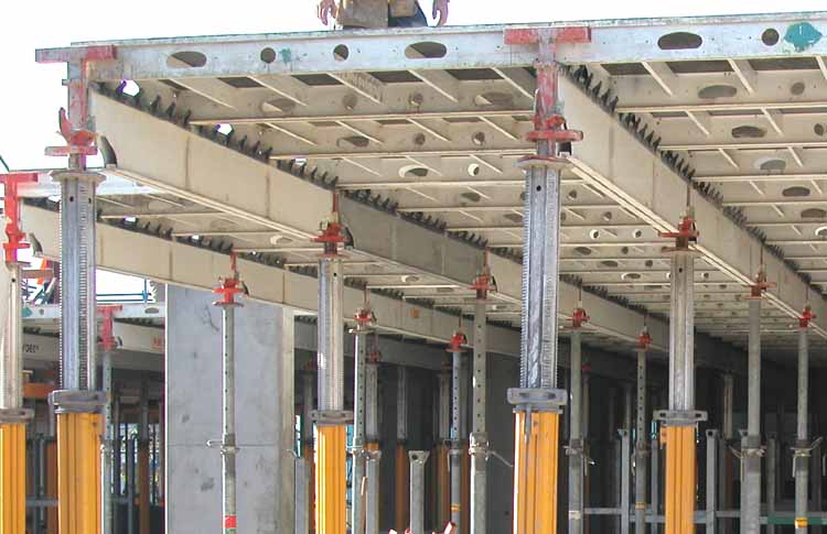
Fixing of Girders & Sheets:
After vertical erection of shoring tower to its required location, the primary girders and secondary girders will be provided on the cross head spindles. Above the secondary girders 18 mm thick plywood sheets will be provided and fixed on top.
Access:
Suitable access shall be provided to and between the formwork. Access shall be provided by portable ladders / hook on ladders / attachable ladders or stair way type ladders. Scaffolding erection team can then access the platform. They will fix the outside guardrails before fully boarding the remainder of the platform. All ladders shall be secured against displacement.
Assigning Personnel:
Competent person shall be assigned for the formwork selection, erection, use, movement, alteration, dismantling, maintenance and inspection. Only assigned and trained personnel shall be deployed to work. It will be ensured that the user is aware of the fall protection methods, belts and full harness, life lines, rope etc.
Training:
Assigned employees shall receive instruction on the particular type of formwork that they are going to use. In the training it will be ensured that focus is given for proper erection, handling, use, inspection, removal and care. Training shall also include the installation of fall protection.
Site management personnel should also be familiarized with correct formwork / scaffolding procedures so they can better determine needs and identify deficiencies.
Dismantling of Scaffolding:
Removal:
- Formwork shall be carefully removed without shock or disturbance to the concrete. No formwork shall be removed until the concrete has gained sufficient strength.
- The minimum periods which shall elapse between completion of placing concrete and removal of forms shall be followed as per project specifications.
- The supports shall not be removed temporarily for the purpose of stripping formwork and subsequently replace them.
Striking:
- Curing time must be kept in consideration while striking of formwork.
- Dismantle the intermediate props.
- Lower the Crosshead props by approximately 4 cm.
- With larger spans, lowering and removal of props shall be started from the slab center.
- Remove crossbeam with erection bar from below and store in pallets.
- Remove plywood and remaining crossbeams and store in pallets.
- Remove the main beams and store in the pallets.
- Remove the crosshead props and store them in pallets.
- The access ways shall be kept free.
- Dismantling shall take place from a safe and secure position.
Lowering:
- The drop heads over large area shall be lowered.
- Wedge shall be released by means of hammer whilst paying attention to direction of wedge.
- There will be a gap/clearance approx. 6cm between the panel and slab underside, after releasing the wedges and lowering.
Edge in fills:
- Striking shall take place firstly on the transverse in fills and then the longitudinal in fills.
- Then the props shall be removed and stored in pallets.
Panels & Girders:
- The removal of panels shall begin in the corner where both in fills meet.
- Dismantle Panel in one field after the other – begin with the middle panel.
- Lift panel and push approx. 10 cm in the direction of the free side pivot downwards and store in pallet.
- The girders shall take down and store in pallet.
- Only drop head props shall remain standing.
Maintenance and cleaning:
In order to maintain the value and operational readiness of the slab formwork over a long time, it shall be ensured that the formwork is carefully handled at all times.
Waste removal & Housekeeping:
- Damaged material Boards shall be removed as per HSE waste management procedures.
- Al Jaber Building operatives will follow good housekeeping guidelines as per site rules and utilize storage areas allocated by Client
General guide lines for proper erection and use
- Supervising the erection of formwork by a person competent by skill, experience and training to ensure safe installation according to manufacturer recommendations and drawings.
- Examine all components prior to erection.
- Defective components should be returned and tagged “DO NOT USE” or destroy.
- All decks should be planked as fully as possible.
- Gap between planks should not exceed one inch.
- Safety guard rails to be erected.
- Prohibit the movement of the scaffolds when employees are on them.
- Maintain the scaffold distance from the over head electrical cables if any
- Ensure that the scaffolds and components are not loaded beyond their rated and maximum capacities.
- Prohibit work until water, oil, grease and other materials that could cause slipping and falls are removed.
- Prohibit erection work during storms and high winds.
- Remove debris and unnecessary materials from platforms.
- Maintain formwork in good condition. Replacement components should be from original manufacturer.
Back Propping:
- The scaffolding / formwork shall be removed within the minimum elapse of time as mentioned in the specifications.
- The previously concreted slab shall be supported by providing back props if there is any further level.
- The back props shall be provided as required, according to the structural calculations done by CONTRACTOR’s Structural Engineer.
- The back props shall be provided according to the attached sketch.
Discover more from Project Management 123
Subscribe to get the latest posts sent to your email.