Below method statement covers the above ground drainage installation activities.
By following this procedure contractor shall ensure that the installation of drainage piping has been carried out as per project contract requirements, specifications and best practices.
It gives details of how the work will be carried out and what health and safety issues and relevant controls are necessary.
Below is complete table of content for a professional method of statement, we are covering few sections on this page.
Table of Content
- Scope of Works
- References
- Location of activity
- Abbreviations and Definitions
- Constraints on Operations
- Roles & Responsibilities
- Method Description
- Materials and Products
- Engineering
- Plant, Tools, Equipment and Welfare arrangements
- Access arrangements
- Emergency/ Incident Procedures and First Aid/ Pollution Control Arrangements
- Communication and Training requirements
- Appendices
References:
- Contract Specifications
- Approved shop drawings.
- DIN 8077 / 1692 Standard.
- BS-3505 class E Standard.
- Inspection and Test Plan.
- Project Safety Plan.
- Project Quality Plan.
- Project Logistics Plan.
- Related International standard (ASME, ASTM -A653A, 653M and ASHRAE standard).
- Local Authorities Regulations
The minimum Personal Protective Equipment (PPE) on project site is:
– Safety Helmet / Hard hat
– Safety Boots
– High-visibility vest
– Gloves
– Safety Goggles/ Glasses
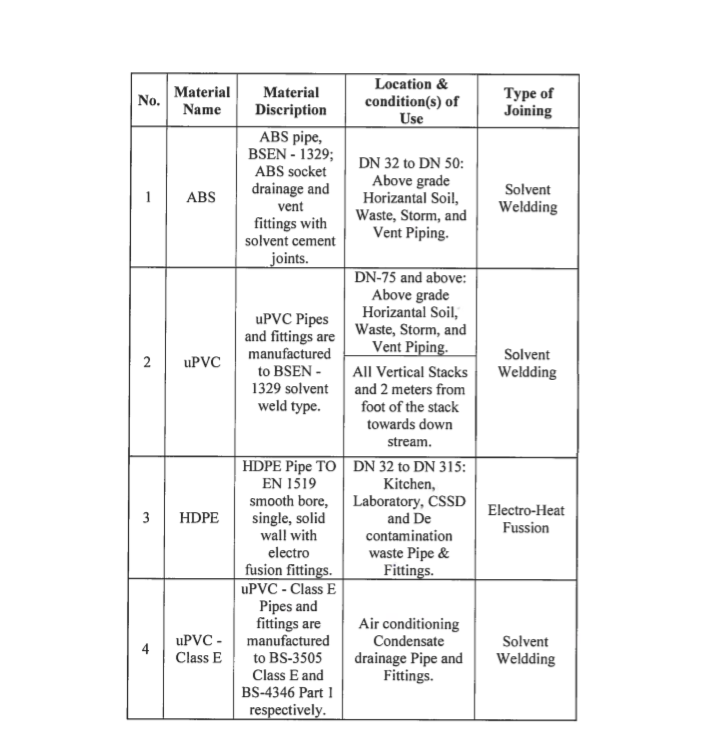
Location of Installation and Pipe Selection:
Horizontal and vertical above ground installations through all the areas in the project as per using various types of material as specified in the specifications and summarized in the below table:
Constraints on Operations
Site working hours will be 8am to 6 pm at start of operations.
Nightshift will be from 6pm to 4 am.
Supply trucks will follow an agreed access to the project.
No lone working is permitted.
Roles & Responsibilities
Project manager shall be responsible overall to complete all MEP works as per specifications, budget, time, & quality
MEP Site Engineers shall be responsible for but not limited to the following important activities:
- To ensure that all the preparation and application works are carried out according to the contract specification and manufacturer’s data sheet(s).
- Ensure that the progressing of works is carried out according to the planned program, and as per the approved Method statement.
- To ensure that all the equipment’s and materials required in executing the works are available according to the planned constriction program.
- Coordinate with the main contractor’s MEP coordinator and safety officer for all safe and proper execution of the work in accordance with the risk assessment.
- To coordinate with the civil team for any area preparation, access, clearance.
Foreman shall be responsible for but not limited to the following important activities:
- To guide and control the tradesmen and charge-hands(s).
- Ensure that work is done as per the approved shop drawing(s).
- To report to the MEP site engineer.
H& S Officer shall be responsible for but not limited to the following important activities:
- Ensure health and safety of the site personnel.
- Ensuring all the necessary PPE available with site personnel.
- Good housekeeping on site.
- Environmental concerns are addressed.
- Responsible for implementation and assurance of the safety and environmental requirements (JSEA).
Quality control engineers shall be responsible for but not limited to the following important activities:
- Inspecting the materials on site as per approved materials submittal prior to installation on site.
- Inspection for the installation as per approved drawings and approved test plans and checklists.
- Preparing test forms for testing on site and updating results accomplished.
- Issuing inspection request within 24 hours before the actual inspection.
- Responsible for the assurance of Quality control, method statement and inspection test plan.
- Controlling the shop drawings flow on site.
Sequence of Activities for Drainage Piping Works
Delivery, Handling and Storage
The pipes and fittings material and its associated material supplied protect against damage during handling, transport, storage and installation.
Material to be delivered to the site store in self supporting framed units.
The pipes material will be stacked as loose with all material parallel (nested).
Material will be stored in clean and closed store for protection and according to manufacturer’s recommendation.
The height of the pipe stack should not exceed seven layers or two meters maximum height.
Stacks should be protected from sun & weather elements by means of placing tarpaulins or similar sheets over them secure fixed to the timber support post, in order to provide protected.
Inspection of Materials in Store
Notify MEP Engineer upon delivery of material at site
All materials shall comply with the approved Material Submittal.
Upon the receipt of materials on site, these shall be inspected by the QC Engineer / Inspector to ensure correctness of material as the Approved Material Submittals and quantities.
Ensure that the materials are handled properly, and protected against dust, dirt and foreign matter.
A material inspection report shall be prepared by QA/QC Engineer/ Inspector for submission to the Consultant for review and acceptance.
Material not complying with the Material Submittal or unusable/damaged duct or fittings will be placed in a quarantined area and clearly labelled ready for manufacturer to replace.
The works shall be executed in accordance with the following methodology and sequence;
Pre Installation Checks
A pre-start meeting prior to the commencement of the works will take place with the Site Engineer, H&S Officer, QC Engineer, Supervisor/Foreman in charge to address the following:
Ensure that the notification to start activity has been issued.
Check and ensure that the area has been surveyed as per approved drawings.
Ensure that the installation area is clean from debris and foreign matter.
Make sure that materials are as per approved Material Submittal.
Ensure that adequate number of tradesmen and proper tools are present.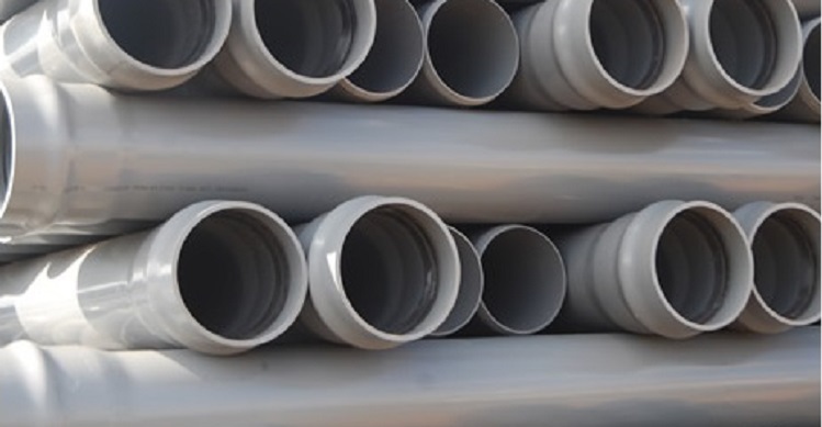
Check that latest approved shop drawing(s) for this installation is present, and all personnel are working off the same drawing.
Ensure that area is safe to carry out the drainage piping work.
Area for materials preparation installation has been identified and procedures will be in place.
Eye wash area near in the fabrication areas in case of workers skin contamination with resin or other chemicals.
Temporary electrical DBs are provided and inspected regularly by the electrician prior to execution of the works.
Ensure that the related mock-up is accepted /approved by the consultant.
Plan well in advance for all fittings and accessories that will be installed to avoid giving any unnecessary/extra joints.
Marking & Installation of Drainage Pipe Supports
Pipes supports, hangers, spacing as per approved shop drawings and specification.
Attachments to the roof slab will be by the means of expansion anchors.
Drill into the concrete and place the expansion anchor.
Thread rods and channel sections will be prepared for installation in the workshop.
Building attachments: insert the powder coated actuated fasteners or structural steel fasteners appropriate for building materials and all cutting edges shall be cut and painted with specified paint.
For full details regarding hangers and supports requirements refer to the separate hangers & supports method statement.
General Installation Guidelines as per Project Specifications
Install cast-iron sleeve with water stop and mechanical sleeve seal at each service pipe penetration through foundation wall. Select number of interlocking rubber links required to make installation watertight.
Install wall penetration system at each service pipe penetration through foundation wall. Make installation watertight.
Install piping above accessible ceilings to allow sufficient space for ceiling panel removal.
Install piping at indicated slopes.
Install piping free of sags and bends.
Install fittings for changes in direction and branch connections.
Install piping to allow application of insulation.
All the pipe work (high level) passing through living areas like bathrooms, bed rooms, offices, lobbies etc. shall be acoustically insulated or acoustically insulated pipes to be used.
All the risers 4 meters upstream and downstream of the foot shall be acoustically insulated.
Also ensure that fire proofing material is applied as required between pipe & sleeve.
Escutcheons to be provided wherever applicable.
Marking / labelling to be done on piping as per standards.
Installation Method of uPVC / ABS Pipes
Mark the location the routing of the pipes base on approved drawing
Pipe work must be installed as per approved drawing clearances clearly indicated make sure the minimum clearances.
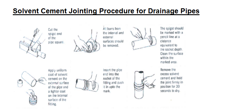
The pipes must be cut off at right angles. The pipes must cut using only the pipe cutter.
Joints for uPVC sections should be sealed using Solvent Cement.
Provide space for expansion / contraction as applicable.
The spigot and socket to be jointed should be carefully examined for any damages which would impair the jointing procedure. Particular attention should be paid to the spigot chamber as for toe – ring jointing procedure.
The spigot insertion depth should be measured as the depth from the mouth to the shoulder of the socket. The insertion depth should then mark on the spigot using marker.
The mounting areas of the spigot and socket should be thoroughly cleaned with rag and absorbent paper until completely dry.
Using a brush of the size recommended apply an even layer of solvent cement to the spigot and socket amounting surfaces.
The cement should be applied in a lengthwise direction and not with circular motion. For joints of nominal diameter 3 and above the cement should be applied simultaneously to the spigot and socket.
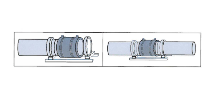
Installation & Welding of HDPE Pipes
All the hdpe pipe welding process to be performed in a fully arranged workshop & not in open area or near to other services.
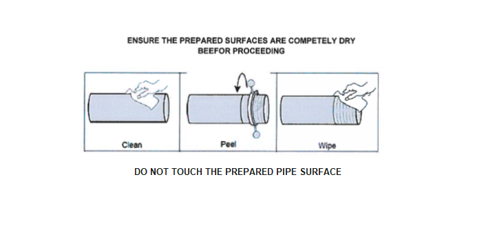
Wipe the prepared pipe surface only with a recommended alcohol wipe to remove any dust residue and other contaminants. For larger diameter pipes use a multiple number of alcohols wipes.
The pipe end(s) and the fitting must be correctly aligned and free of any bending stress. Use pipe clamps, or other suitable means, to secure the pipe(s) so they cannot move and ensure that the fitting is satisfactorily supported to prevent it sagging during the fusion procedure.
Connect the control box output leads to the fitting terminals and check that they have been fully inserted.
The jointing time is generally indicated either on the fitting or on a data carrier supplied with the fitting. Check that the correct time is shown on the control box display. If required for the control box, enter the fusion jointing time into the control box timer.
NOTE: Automatic control boxes are available which obviate the need to enter the fusion time.
If the control box is equipped with a barcode reader or barcode scanner, scan the fusion data barcode into the machine to ensure a fully automated and controlled data entry. Barcode reading control boxes automatically adjust for variable temperature conditions. For manual input of the heat fusion time into the control box, refer to the manufacturer’s parameters, supplied with the fitting.
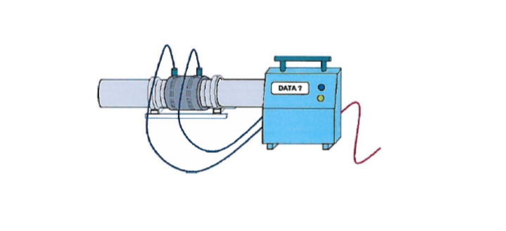
Press the start button on the control box and check that the heating cycle is proceeding as indicated by the display.
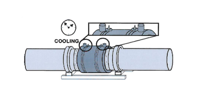
On completion of the heating cycle, both melt indicators within the processed part of the fitting should have risen.
If there is no apparent movement of either indicator the joint could be unsatisfactory – refer to discussion on electrofusion indicator pins below.
Flexible Joints
Ensuring that thermal movement at any joint does not exceed the allowable axial movement of the connector.
Construction of flexible connectors shall be Neoprene inner tube and outer cover with multiply nylon tyre cord fabric reinforcement.
Standard duty flexible connectors shall be rated for 1600 kPa working pressure and 2400 kPa test pressure, up to 105 °C. Manufacturer shall certify that each unit is individually pressure tested.
Connectors for pipe size 65 mm and above shall be of spherical single bellow design with captive steel floating flanges to facilitate alignment. Flanges shall be epoxy powder coated. Bellows shall have steel wire reinforcement at the lips.
Connectors for pipe size up to 50 mm shall be of double bellow design with threaded ends. End connections shall be triangular flanges made from forged steel and epoxy coated. Ml unions will not be accepted.
Where flexible connectors are connected to unanchored piping or isolated equipment, provide control units when pressure exceeds the maximum recommended for this application by the manufacturer.
Full details regarding the expansion joints bellows & connectors will be submitted among detailed selection calculations and method statements upon determining the supplier and material selection.
Cleanouts On Soil Waste Vent and Storm Water Installation
Install cleanouts at each change of direction of drainage pipes, greater than 45 degrees, inside the building, and where indicated on the drawings. Cleanouts shall be not more than 30m apart in horizontal lines. A cleanout shall be provided at or near the foot of each vertical waste or soil stack.
Cleanouts on concealed piping shall be extended through and terminate flush with finished wall or floor. Pits or chases may be left in the wall or floor, provided they are of sufficient size to permit removal of the cleanout plug and proper cleaning of the system.
Where it is necessary to conceal a cleanout plug, a heavy duty stainless steel covering plate shall be provided, which will permit ready access to the plug.
Cleanout plugs shall be of heavy duty stainless steel with seal and lock. Final finish shall be to the approval of the consultant engineer.
All the cleanouts shall be of the same nominal size as the pipe up to 100 mm pipe diameter and not less than 100 mm for larger piping.
Cleanouts shall be so installed that there is a clearance of not less than 450 mm for the purpose of rodding and cleaning.
Leakage Testing of Drainage Piping System
The drainage system will be tested for leakages before encasing in concrete.
Warning barriers shall be erected around the test area.
All test points will be plugged shut with test plugs.
It will be ensured that all bends, changes of directions and ends of run are restrained against movement as water exerts a thrust force equal to static pressure times the area. This thrust can dislodge joints if not properly restrained.
A temporary test stack of 3 m height will be installed at the desired test point (highest point).
Marking to be done outside of stack if stack is of bigger length.
Water will be filled into the system slowly through the test stack, allowing the air trapped inside the pipe to escape. Failure to remove this air will cause faulty test results.
The water shall be filled to the full height of test stack and the joints shall be inspected after minimum 60 minutes to assess if any water leakage has taken place. Top of stack to be covered to avoid anything falling inside.
If any water leaks are found, the joint shall be disassembled and inspected to determine if the correct procedures were followed.
The test shall be repeated after rectification of any leaks.
The pipe will be filled with water and allowed to stand for 8 hours before the Employer’s Representative is invited to inspect the installation.
After approval from Employer’s Representative, the encasement for the drainage system shall be done prior to backfilling.
Communication and Training Requirements
A Pre-construction conference will take place to brief all on this method statement.
All operatives will attend the Project Safety induction prior to commencing work on site.
As a minimum a Daily Briefing will explain and discuss:
- What the day’s work is for the gang and individuals
- Planned sequence of work
- Plant requirements
- Materials requirements
- Trades handing over/ handing back
- Other trades and their work in the vicinity
- Seeking feedback on Health and Safety issues and any near misses or accidents reported or not yet reported.
Frequent tool box talk for personnel involved in the activity to insure full awareness, high quality and productivity, & to decrease accidents.
Appendices
Job Safety Analysis JSEA
Inspection & Test Plan ITP
Inspection Check sheet
Leakage Test Certificate
Project Logistics Plan
Discover more from Project Management 123
Subscribe to get the latest posts sent to your email.