The following Method Statement describes the procedure and equipment required for the false ceiling works.
Below civil method statement covers following types of false ceilings:
- Gypsum and Cement Board False Ceiling
- Beam Grid System False Ceiling
- Baffle ceiling
- Ceiling Tiles, 600 x 600mm and 600 x 1200mm
Necessary Tools & Equipment
Following tools shall be arranged before the starting the works for false ceiling installation:
- Drilling Machine
- Scaffolding
- Cutting tool (tin snips)
- Self-leveling laser
- String/Chalk line
- Circular saw
- Hammer/chisel
- Screw driver
- Knife
- Rotary or hammer action impact drill
Installation Procedure for False Ceiling Works
GYPSUM AND CEMENT BOARD FALSE CEILING:
Handling and storage:
- Plasterboards are supplied on plasterboard stripes (under layers)
- Packs (pallets) should be lifted with a fork lift truck, the fork being set so there is even weight distribution and no deformation of the pack.
- Ensure handling equipment is of adequate capacity and that the personal are advised of handling procedures and safety clothing.
- Care should be taken all times to avoid strain to handles.
- Boards should not be lifted at the short edges or carried horizontally.
- Carry the boards on the edge, two persons per board by supporting on long edge and gripping upper edge to avoid breaking due to flexing.
- Plasterboards must be stored flat in a clean dry environment on a flat surface.
- The stripes should be wide and placed at the maximum centers.
- Plasterboards are not designed to support body weight.
- Fixers must work from an independent support system.
- Avoid exposing to sunlight otherwise the paper will change the color.
Leveling & Fixing of Wall Angles:
- Finished floor level marks must be available in all areas Primary Points only and elevation by Main Contractor by using level instruments.
- So many points will be marked by measuring the required ceiling level from the existing marks in item (a) by using measuring tapes. The maximum points spacing should be five meters. Then, a continuous line will be marked between the points by using chalk line.
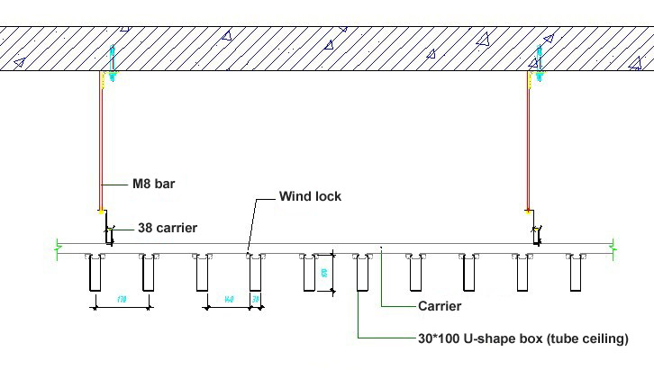
- Wall angles will be fixed on the marked lines to the wall by using concrete nails of 25mm length and will be fixed to the wall at a spacing of 300mm starting at 100mm from both ends of wall angles.
Fixing of Suspension Grid:
- After receiving clearances from electrical and electro-mechanical works, ceiling nails will be fixed to the ceiling structure by using shooting gun machines at a spacing of 900mm distributed according to the ceiling layout on the approved shop drawings.
- Galvanized angle will be inserted to the ceiling nails from one end. The other end of the angle will be screwed to the Main Runner.
- The Main Runners will be fixed at 900mm spacing. The runners are galvanized steel of 38mm wide U – channel sections. Finally the galvanized furring channel will be fixed to the main runners at 600mm spacing using wire clips.
Fixing of Gypsum Board:
- The Upper layer of 12.5mm thick Gypsum Board will be fixed on the Furring Channel by Dry Wall screws at 200mm at the tapered edges and 300mm at the center of the board.
- The Lower layer of 12.5mm thick Moisture Resistant Gypsum Board will be fixed on the Furring Channel by dry wall screws at 200mm at the tapered edges and 300mm at the center of the board.
- Two inches Fiber Tape will be fixed on the tapered edges of Gypsum Board Joints.
- Special joint compound will be applied for covering edges of gypsum joints and spotting fasteners.
- MEP marked holes will be cut in Gypsum Board for services according to approved sizes requirements (such as lights, sprinkles, etc.) as per electrical and mechanical requirements.
- Decorative openings will be cut in gypsum board as per approved sizes requirement.
Gypsum Board Vertical Bulkheads and Cove Light:
- Ceiling tracks 52 x 0.55mm thick will be fixed using partition nails.
- Vertical studs 50 x 0.55mm thick will be inside the tracks every 600mm center to center wherever is possible using steel screws.
- In as similar way, the lower tracks will be fixed to the vertical studs by steel screws.
- Moisture Resistant Gypsum Board will be fixed to the facing of Metal Framing by Drywall Screws.
- Special joint compound and fiber tape will be applied to cover Gypsum Board joints (Gypsum Board at the same plane) and spotting screws.
- Steel Corner Tape with joint compound will be applied to cover the exposed corners of Gypsum Board.
BEAM GRID SYSTEM FALSE CEILING
Durlum metal ceilings are usually delivered on pallets.
It is advisable to leave the metal panels on the pallets as long as possible.
If the pallets have to be opened, the durlum metal panels should always be positioned on the long side, it can then be placed carefully against the wall, do not store flat.
Storage must be carried out such a manner that there is no chance of damage.
The assembly of the ceiling panels must not start until all dust-producing work has been completed.
Mounting Sequence:
- Ceiling layout plan as per the approved shop drawings.
- Cross-check the ceiling layout plan against the on-site situation.
- Preparing a bill of materials, including a suitable work plan and retrieval/order of the materials required.
- Determine the required suspension points, the corresponding suspension distance can be taken from the detailed descriptions of the individual ceiling system
- Mark the dowel mounting holes and drill them.
- Shorten the provided fastening elements, such as the M6 threaded rod to the intended length.
- Use the layout plan to determine in which direction the cross reinforcement profile are laid.
- The respective primary profiles are mounted at the right angle to the secondary profiles, to this end, the system-specific connecting elements are used.
- Attachments or other loads are to be mounted separately.
- For logical reasons these parts are integrated during the mounting process.
Assembly Sub Construction:
The general distance for mounting the perimeter trim is max. 500mm.
This general distance is less, depending on additional loads, the type of wall and special requirements.
- Level and outline given ceiling height.
- Outline the upper edge of the perimeter trim.
- Mark the drill hole.
- Drill a hole for the dowel.
- Secure the perimeter trim with a dowel.
- Cleaning mitre cut the edges of the perimeter trim profiles.
Assembly of primary profile
- Outline the axis grid of the junction points according to the reflected ceiling plan and layout plan.
- Level and outline the specified ceiling height.
- Drill the holes for dowels.
- Mount the dowels.
- Cut the threaded rod M6 to the required suspension height.
- Screw in the threaded rod to the stop.
- Screw the hexagon nut M6 onto the threaded rod.
- Slide the junction point CK 2003 with the mounting bracket onto the threaded rod.
- Fasten the junction point CK 2003 on the threaded rod with a rigid and self screwing screw connection M6.
- Place the junction point horizontally, vertically and align for the specified ceiling height.
- When adjusting the height, observe the permissible height tolerances according to EN 13964, readjust if necessary.
- Insert the C-channel hook-on profiles C 2002 at the wall bracket to the required length and fasten them at the wall bracket for C-channels C 2009 by means of the dowels at the partition walls.
Assembly of the ceiling panels:
- Wear clean gloves.
- Remove the protective foil from the ceiling panels.
- Insert the ceiling panel with the short side diagonally from below over the C-channel profiles.
- Lower the ceiling panel slowly and put it down on the C-channel profiles.
- Check the perpendicularity of the joint and its even width; if necessary, re adjust the junction points CK 2003 to the required axis pitch.
BAFFLE FALSE CEILING
Storage:
- Durlum metal ceilings are usually delivered on pallets. It is advisable to leave the metal panels on the pallets as long as possible.
- If the pallets have to be opened, the durlum POLYLAM should always be placed on the underside.
- Storage must be carried out such that damage is excluded.
- The assembly of the ceiling panels must not start until all dust producing work has been completed.
Mounting Sequences:
- Ceiling layout plan as per the approved shop drawings.
- Checking ceiling lighting installation plan versus structural conditions.
- Preparing a bill of materials, including a suitable work plan and retrieval/order of the materials required.
- Determine the required suspension points, The corresponding suspension distance can be taken from the detailed descriptions of the individual ceiling system
- Mark the dowel mounting holes and drill them.
- Shorten the provided fastening elements, such as the M6 threaded rod to the intended length.
- Use the same procedure when mounting the wall brackets, mounting distance about 400-625mm.
- Usually the panel layout should be started from the center of the roomin order to be able to compensate the tolerance of the room.
Assembly Sequence:
- Set ceiling nails.
- Mount the Nonius upper parts or the threaded rods on the raw ceiling.
- Nonius suspension:
- The lower Nonius part U 1370 is screwed together with the primary profile U 1040 and secured against loosening.
- The mounting level of the primary profile is established via a laser or hose level.
- The upper Nonius part is screwed to a raw ceiling with ceiling nails and bent. The length determined is accordance with the suspension height.
- The Nonius upper part and the Nonius lower part are slid into each other, the height is adjusted and the two parts are connected using two safety pins U 1372.
- The adjusted lower Nonius is now screwed to the profile U 1040 with an M6 screw.
- The longitudinal joint U 1040 is slid into the joint of the primary profiles.
- Wall connection takes place via U 1042, which is screwed to the wall and to the profile.
- The 75-POLY-UTS is connected to the U 1040 via M6-screws/nuts and secured against loosening.
- The centring cone on the front face of POLYLAM baffle is twisted out with a screwdriver.
- The POLYLAM baffles are hooked on to the 75-POLY-UTS in an interlocking manner and connected at the longitudinal joint via the centring cone.
- In as far as intended, the anti-lifting lock is placed on the baffle and secured with a self tapping screw, at least 2 per baffle.
Distance of the Suspension: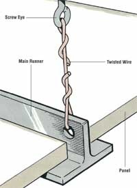
Distance of the AP primary profiles according to EN 13964:
Recommended every 1500mm as directly mounted suspension
Distance of the AS secondary profiles according to EN 13964:
Recommended at least every 1500mm with min 2 per baffle.
Distance of the AH suspension points:
Recommended every 1000mmas directly screwed to the primary profile U 1040.
INSTALLING CEILING TILES 600 x 600mm and 600 x 1200mm
Leveling and Fixing of Wall Angles:
Structural wall must be plastered or finished by any other finishes required by client.
Finished floor level marks must be available in all areas by using level instruments.
Points will be marked on walls by measuring the required ceiling level from the existing marks using measuring tape.
The maximum points spacing should be five meters, then a continuous line will be marked between the points by using chalk line.
All high level works including fire stopping, forming of penetrations to be completed.
Powder coated W-shape wall angles will be fixed on the marked lines to the structural wall or partition walls by using concrete rails or black Screws with plastic anchor of 25mm length and will be fixed at a spacing of 300m centre to centre.
Testing of hangers will be concluded as per specification & refer to field quality control requirements.
Location of access hatches to be allowed when installing hanging supports.
Fixing of Suspension Grid:
After receiving clearances from MEP Subcontractors, ceiling nails will be fixed to the ceiling structure by using shooting gun machines at spacing of 1200mm distributed according to ceiling tiles layout on the approved shop drawings.
Hooked steel rods of diameter 4mm will be inserted to the ceiling nails from one end.
The other end of the rods will be inserted in a steel adjustment clip.
Length of the rods will equal to the height of structural ceiling to the false ceiling less 200mm.
Another set of 4mm diameter steel rods will be inserted to the other end of each adjustment clip.
The length of these rods is 300mm in which they have hooked shape at the other end.
Installing of these hangers should be plumb & free from contact with insulation or other objects within ceiling plenum that are not part of supporting structure or of ceiling suspension system.
In case width of services (A/C ducts…) interfering with the location of hanger at required spacing, a bracing system will be provided around such services & then the hangers will be attached & suspended to the suspension system.
The hooked end of the rods will be hanged into the holes of the vertical flange of the main runner steel T-grid suspension with a minimum of four tight turning.
Length of the main runner is 3600mm in long span rooms.
The main runners will be laid consecutive by connecting them to each other at their ends by riveting 100mm steel thin plates to the vertical flanges of the consecutive main runners.
Finally, cross T-grid runners of the length 1200mm will be fixed to main runners by inserting cross runners both ends in the opening holes of main runners every 600mm.
Then the cross T-Grid runners of length 600mm will be inserted between the cross T-grid runners of length 1200mm to form a module size of 600 x 600mm as per catalogue.
Discover more from Project Management 123
Subscribe to get the latest posts sent to your email.