All workers to attend safety induction conducted by main contractor and specific training on the safe installation methods. Install HV Panels as indicated on the approved shop drawing and as per specification and according to manufacturer’s recommendation.
Site Engineer and Site Supervisor will give necessary instructions to tradesmen (electrical technician) and provide necessary approved construction/shop Drawings of latest revision along with coordinated layouts.
The Site Supervisor/Foremen will also check that proper tools and equipment are available to carry out the work and are in compliance with contract specification.
Site Supervisor also explains to the tradesmen regarding safety precautions to observe.
Working on live power cables/equipment is not allowed. ELCB shall be used in temporary panel boards; industrial connectors/sockets for temporary power cable connections.
Arrange below tools and equipment for the electrical installation of high voltage panels.
- Fork Lift for transporting HV Panels
- Lifting equipments
- Pallet trolleys/rollers
- Lifting bells
- D shackles
- Drilling Machine
- Hammer
- Spirit Level
- Hack saw
- Leveling Instrument
- Spanners/Torque Wrench
- Wrenches
- Jack Trolley
Electrical HV Panels Installation Sequence
Refer to approved Offloading and Lifting of Major Plant Room Equipment Strategy Plan for shifting of HV Panels and Accessories.
Lifting procedures recommended by manufacturer will also be taken into consideration (included in approved material submittal).
HV Panel units will be off-loaded to the lay down areas which are nearest to the location of the HV rooms and can be easily mobilized moving it towards the exact location or the HV rooms by using forklifts or heavy duty jack trolley as
per manufacturers recommendations and project specification.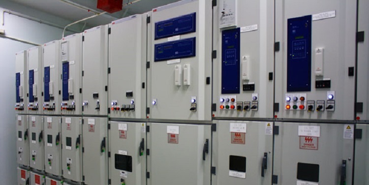
The HV Panels shall be installed by competent qualified electrical technicians and be witnessed by the manufacturer’s representatives if necessary as per manufacturer’s recommendations and project specifications.
Template to be prepared prior to marking of location of HV Panels as per approved shop drawing and project specifications.
Each enclosure unit shall be identified by a label, which clearly indicates its function and electrical characteristics.
HV panels must be installed in adequate area having wide clearance avoiding obstruction for other services and future maintenance use.
Install HV Panels in HV Room as per approved detailed shop drawings and project specifications and be monitored by manufacturer’s representatives.
Ensure that prior to installation the HV Room is ready, clean and in acceptable condition. Report immediately any discrepancy in civil works to main contractor.
Check the HV Panels and Accessories as listed below:
- HV Panels Enclosures
- Circuit Breakers (withdrawable)
- Bus Bars
- Contactors
- Current Transformers
- Voltage Transformers
- Protection Relays
- Measurement Meters
- Auxiliary Contact
Marking to be made on the floor, visibly trace according to the relevant approved shop drawing perimeter of all units making the HV Panels and Accessories taking the minimum wall and obstacle clearances into account and check the floor levels.
Position anchor bolt on the floor as per arrangement shown on approved detailed shop drawing. Make sure to position the individual cubicles at its right location. Check alignment.
Level the units and then bolt them together in the front and rear part.
Use appropriate size of bolt to fix HV Panels together (front and rear be bolted). Tighten bolts with adequate torque using suitable nuts and washers.
Join the cubicles with the bus links. Check the final alignment.
Busbar Connections in HV Panels
- Install the busbars panel by panel. Screw on the individual busbar elements one above the other (depending on the system layout) and in line with the flat branch conductor.
- Bolt one holder to each end of the busbars to support insulating cover and the screws for holder must be tightened with a lower torque.
- Position insulating covers and lids over the relevant bolted joints and slide the lid onto the cover until it clicks into place (for insulated busbar only).
- Finally, do the tightening of all bus links joining bolts with torque wrench (standard torque).
Ensure that HV Panels are correctly installed, vertical sections are joined together, rigidly assembled, and bus bars are jointed together and tightened with adequate torque.
Withdrawable circuit breaker parts must be inserted and the control wirings connected.
Ensure that the Cable Inlets should be provided at the bottom of each functional unit of HV Panels.
Ensure the installation of HV Panel have the functional units:
- An air – insulated, metal-enclosed, metal clad cubicle, for indoor use.
- A withdrawal switchgear device with vacuum breaking, sealed for life.
- A protection and control system.
Ensure that the functional unit shall be the following:
- Underground cable feeder: by circuit breaker
- Switchboard coupling: by circuit breaker
- Busbar voltage measurement
- Transformer feeder: by circuit breaker
Check modular arrangement of indicating instrument, contactors, relays, current transformers, voltage transformers, meters and other items mounted in compartments of Switchgear. Make sure no damage occur during erection and installation as well as per installation manual and project specifications.
At this point, proceed with the termination of MV cables from supply side and LV cables going to the Transformer side as per project specification and approved shop drawings and manufacture’s recommendations.
Make sure to use the approved propriety termination kit, shrouding kit and armour terminating gland. All glanding and termination of cables will be done by competent and accredited electricians and Liaise fully or witnessed if necessary by the regulatory authority for the cable connections.
Make sure the Cable lugs shall be of correct size and type and be joined by means of hydraulic crimping tools.
Ensure the armour terminating gland shall be complete with an earth tags, lock nuts and shrouds.
All incoming MV Cable terminations shall be from below entry for ground floor and for 2M level shall be on the top entry.
Ensure that all the breakers provide volt free contacts for BMS monitoring to indicate their status (open, closed, tripped & earthed). Check earthing is provided as per specifications.
Upon completion of installation, inspect interior and exterior of HV panels, remove paint splatters and other spots, dirt or foreign bodies/debris if any.
Each enclosure unit shall be identified (tagging / labeling) which clearly indicates its functions, electrical characteristics, and dangerous /hazardous sections, as per projects specifications.
Touch up minor scratches and mars to match original finish.
Clean the Switchgear (HV Panel and Accessories) thoroughly.
After installation, cover the panels for switches & dimmer modules with polythene sheets as protection against dirt, moisture, and other construction debris and as per approved IAQ Plan.
HV Panel Installation Checklist
- Check the HV Panels installed is as per approved shop drawings and submittal.
- Check labeling/tagging of HV Panels is as per equipment schedule.
- Check orientation of HV Panels is correct with sufficient space for operation & maintenance.
- Check that panels are free from physical & mechanical damage.
- Check for mounting of Panels, correct size of plinth has been prepared and leveled at correct location.
- Check conduit stub-up on the plinth has been cut and protected with suitable covering for earthing and as applicable.
- check all the holding down bolts are correct sized and installed at correct positions as per panel requirements.
- Check that panels are plumb and level.
- Check that mechanical operation of circuit breaker is OK.
- Check that panel earthing is complete.
- Check that panel door interlocks are provided and operational.
- Check interior and exterior of panel/boards are clean.
- Check Protective Conductor connected to the panel and continuity is verified.
- Energization, testing and commissioning will be done by the specialist contractor/supplier in direct supervision of MEP team.
Discover more from Project Management 123
Subscribe to get the latest posts sent to your email.