This Fire Hose Reel & Cabinets Testing and Commissioning Method Statement is to provide guidance in carrying out and controlling the testing and commissioning of Fire Fighting system for the project, in accordance with the approved Project Quality Plan, contract specifications and Commissioning plan.
The Test Involves Testing of Fire Hose Reel, Cabinet and Fire Extinguishers.
Necessary water for Fire Fighting system is supplied by the domestic/sprinkler water storage tanks as per quality designed and estimated, necessary Fire pumps are provided at Basement level to pressurize the fire fighting network.
The fire fighting water reserve available at all times.
A set of one (1) main electric pump, one (1) stand-by electric pump and one (1) jockey pump will keep the water of the wet riser fire fighting Fire Hose Reel network under the required pressure and separate.
Fire Pump is Patterson Make with capacity of 125 GPM @ 16 Bar.
The entire building is provided with independent complete fire fighting systems that include the following:
- Breeching Inlet System
- Fire extinguishers
- Fire Hose Cabinets & Hose Reel
Commissioning manager is responsible for entire pre-commissioning and commissioning of the fire fighting system.
All necessary manpower, apparatus and instruments which are required for Precommissioning and commissioning activities shall be supplied by commissioning team.
He leads, plans, schedules and coordinates the Commissioning team to implement the procedure for Fire Fighting System commissioning.
Necessary Instruments & Tools
- Valve operating keys
- Plumbing Tools (wrenches)
- Calibrated Pressure Gauges
- Drums 300 liter to 500 liter
- Cap Gauge
- Static Gauges for verifying cabinet’s internal gauges
Hose Reel Pre Commissioning Phase and Checks
Before commissioning the system the following shall be ensured.
a) The pressure testing of the pipes are complete. (signed off sheet to be provided)
b) The installations of Fire hose reel, Landing valves, accessories and associated pipe works are completed. (Signed off sheet to be provided)
c) Confirm that hose reel and associated valves are located in accordance with the approved drawings.
d) Confirm that equipment is clean and undamaged.
e) Confirm Portable fire extinguishers are installed as per the approved drawings.
f) Ensure that Fire hose reel and all other accessories are ready for putting the system in service.
g) Check that all the Fire hose reel are free from obstructions and rust if any.
h) Ensure that all System equipment’s and devices are properly identified by tags / labels.
i) The system fire pumps are to be commissioned, signed off and available for use to pressurize and supply the system. (Signed off sheet to be provided)
j) Check all Landing valves are closed.
k) Check all hose reel gate valves are closed
l) Check all supports are installed
m) Adjust pressure restricting mechanism for an outlet pressure as per site specification.
n) Standpipe Installation Certification should be signed off.
Testing and Commissioning Phase
Flushing of the system:
a) Flush the system into three sections:
- High Pressure lines up to PRV Stations
- Low Pressure lines up to zone control valve and hose reel.
- Sprinkler lines inside the floors after the zone control valves.
b) Flush the pipe work with plain water to remove construction debris prior to running the system.
c) After the main system have been thoroughly cleaned, flush risers, feed mains, cross mains and finally the branch lines.
In multi level starting at the lowest level and working up.
Branch line flushing in any storey can cross main in that storey, allowing one level to be completed at the time following this sequence prevents drawing obstructing material into the interior pipe.
d) Pre-cleaning stage water will be filled through temporary pump from fresh filing water tank.
At this stage the entire system shall be drained. All the flush water discharged off via the system bleed off valve to the temporary holding tank and disposed off suitably.
This step shall be repeated until the entire system is free of all free standing water.
Flushing velocity
a) Hydraulically calculated water demand flow rate of the system, including any hose requirements.
b) Flow necessary to provide a velocity of 10ft /sec (3 m/sec).
c) Maximum flow rate available to the system under fire condition.
Firefighting Equipment Installation Testing & Commissioning Package – Download Editable Files
Commissioning Checks/Procedure for Fire Hose Reel
- Use the pressure reducing valve to set an outlet pressure of 4.5 bars.
- Once the hose reel piping is under pressure and tested, a flow test will be conducted to ensure proper operation of the hose reel.
- Unwind the hose from the hose reel, and after removing 2-3 meter of hose from the hose reel, the automatic valve will open.
- Fully Open the nozzle and ensure that the flow and pressure at the nozzle of the hose from the reel.
- Check the pressure reading in the pressure gauge installed with the hose reel.
- With the discharge valve closed, slowly adjust the PRV to give the required pressure.
- Repeat steps 3-4 for all units simultaneously.
Commissioning Checks/Procedure for Landing Valve & Fire Hoses.
Unwind the 2 ½ ‘diameter fire hose and connect one end of fire hose to branch pipe and the other end to the outlet of the landing valve.
Slowly turn the hand wheel of the landing valve, unit a constant flow through the branch pipe outlet is achieved.
Ensure the flow and pressure at the outlet of branch pipe.
Witnessing and verification as per the project approval protocol
Set an outlet pressure to 6.9 bars.
Repeat Steps 1-4 for all units simultaneously.
Commissioning Checks for Potable Fire Extinguishers
- Location in designated place
- No obstruction to access or visibility
- Operating instructions on nameplate legible and facing outward
- Safety seals and tamper indicators not broken or missing
- Examination for obvious physical damage, corrosion, leakage, or clogged nozzle
- Pressure gauge reading or indicator in the operable range or position
- Hazardous Materials Identification Systems (HMIS) label in place
Main Drain Flow Test
The main drain valve shall be opened and shall remain open until the system pressure stabilizes.
The static and residual pressure shall be recorded on the contractor’s test certificate.
Manual Valve Test
Each valve intended to be manually opened or closed shall be operated by turning the hand wheel crank or wrench for its full range and returning it to its normal position.
Hose valve caps shall be tightened sufficiently to avoid leaking during the test and removed after the test to drain water and relieve pressure.
Pre-Commissioning Checklist / FHR & Landing Valve, Breeching Inlet & Fire Extinguishers
Confirm that inspection of the installation of the complete system is completed and accepted or signed off by designated approvers.
Confirm that the Fire Hose Reel & Cabinet System piping has been flushed and pressure tested.
Check all landing valves are closed.
Check all hose reel gate valves are closed and the hose is properly winded to the reel.
Check the signage/identification tags are in place.
Check the fire hose reel : hose, hose nozzles, isolation valves, pressure reducing valves and Fire extinguishers are in place, undamaged, and in good condition
Check the Fire Brigade Breeching Inlet plainly visible.
Check the Fire Brigade Breeching Inlet for easy accessible.
Check the Fire Brigade Breeching Inlet caps/plugs are in place.
Check the Fire Extinguishers are full and pin is in place
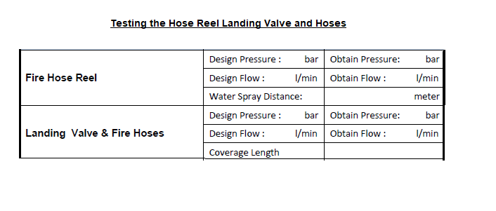
Fire Protection System Commissioning Test Sheet / Fire Hose Reel/Landing Valve System
- Use the pressure reducing valve to set an outlet pressure of 4.5bar.
- Once the hose reel piping is under pressure and tested, a flow test will be conducted to ensure proper operation of the hose reel.
- Unwind 2‐3 meter of the hose from the hose reel, the automatic valve will open.
- Fully Open the nozzle and ensure that there is water flow and pressure at the nozzle of the hose from the reel. Check the pressure reading in the pressure gauge installed with the hose reel
Landing Valve & Fire Hoses
Unwind the 2 ½ ‘diameter fire hose and connect one end of fire hose to branch pipe and the other end to the outlet of the landing valve.
Slowly turn the hand wheel of the landing valve, unit a constant flow through the branch pipe outlet is achieved.
Ensure the flow and pressure at the outlet of branch pipe.
Commissioning Inspection Checklist Fire Hose Cabinet
- Flush the pipe work with plain water to remove construction debris prior to running the system
- Ensure all components of the Fire Hose Reel cabinets are properly installed. (Landing valves, hose reels,
extinguishers and fire hoses) - Check pressure in all floors by using special adapter with calibrated pressure gauge. Record the data in the Test sheet.
- Open the lock shield valve for each hose reel and adjust its pressure to 4.5 bar through the PRV using the special nozzle with pressure gauge.
- The water throw should be 6 meters (check as required to avoid damage to finishes.)
- Check all the extinguishers for certification (inside pressure and hose connections also to be checked)
- After completing these checks, the fire pumps should remain in the auto position.
Commissioning Test Sheet / Fire Hose Reel, Breeching Inlet and Fire Extinguishers
- Prior to testing make sure that the fire pump commissioning have been done and signed off.
- Ensure all the components of the fire cabinets are installed properly (landing valves, hose reels, extinguishers & fire hoses).
- Check pressure in all the floors by using special adapter with calibrated pressure gauge and recorded.
- Open the lock shield valves for each hose reel and adjust its pressure through 1″ PRV using special nozzles with pressure gauge and recorded.
- Check the required pressure as per standards for the setting of PRV.
- Check the minimum distance that the water should discharge from the hose reel nozzle.
- Confirm the required pressure is available at the outlet of the landing valve and record.
- Check all the fire extinguishers for certification (inside pressure & hose connections also to be checked).
- After completing all the above steps, keep fire pumps in auto position and keep under observation.
- Confirm all operating devices and equipment’s are tested for proper function in accordance with manufacturer’s recommendations.
- Visually check the indication of Fire alarm signal in the fire alarm control panel.
- Check and confirm “Commissioning Certificate” is obtained after commissioning of the system.
- Confirm the system is left in service.
Commissioning Checklist for Fire Extinguishers
- Location in designated place
- No obstruction to access or visibility
- Operating instructions on nameplate legible and facing outward.
- Safety seals and tamper indicators not broken or missing.
- Examination for obvious physical damage, corrosion, leakage, or clogged nozzle.
- Pressure gauge reading or indicator in the operable range or position.
- Hazardous Materials Identification Systems (HMIS) label in place.
Firefighting Equipment Installation Testing & Commissioning Package – Download Editable Files
Discover more from Project Management 123
Subscribe to get the latest posts sent to your email.