This civil work method statement is prepared to ensure that construction of buildings for the project shall comply on plans specifications and all relevant standard and code requirements in the execution of different work activities to be performed in the construction of buildings and other relevant structures associated with the project in general.
In addition this document will serve as a tool to guide all technical personnel and layman to execute proper construction procedures in compliance with the quality and safety plans for the project.
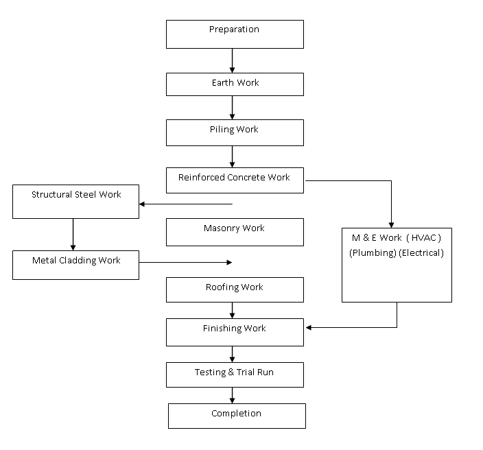
To summarize the process building work is depicted by the following flow chart:
Preparation for Building Construction Works
Temporary yard such as stockpile and fabrication yard for building work shall be prepared within the site after soil improvement.
Location and plan shall be considered to avoid traffic and congestions during mobilization of materials, machines and obstruction to construction during the course of different activities in the site.
It is necessary to set up a fabrication yard in order to carry out the fabrication of reinforcing bars, form work, steel frames and so on. And also, those fabricated, cast, assembled products will be temporarily stocked at the Stock yard. The yards will be graded flat at the designated area and with adequate drainage.
Joint survey with the consulting engineer’s representative shall be carried out to establish control points and confirm the coordinates and elevation prior to the commencement of the construction works.
After confirming the coordinates and elevations of all the building location, survey location for piling and excavation shall be carried out each stage of the works.
Earth Work Method
Excavation work:
Excavation shall be done in a safe and sequential manner on the basis of the prepared plan drawings and in accordance with the instructions by the consulting engineer.
The excavation method is either machine or manual cut, and care is to be taken not to disturb the soil below the supporting ground.
If deep trenching needs shoring, proper lateral sheeting and struts shall be provided for safety.
During excavation, drainage ditch shall be provided and sloping down to sump pit to prevent flooding within the work area in case rain occurs.
Earth excavation with sloped roof and surface drainage to avoid scouring off part of excavation pit.
Unsuitable material and waste matters shall be removed from site to the waste yard in accordance with the specification requirements.
After excavation, the bottom surface of pit shall be compacted to not less than 95% of maximum dry density by vibratory plate compactor and the slope shall be trimmed off to avoid collapse of pit wall.
Backfilling Work Method
Approved suitable material should be used for backfilling. Compaction standard shall be employed in the execution of this work.
Fill materials shall be distributed evenly to the backfill area to a specified thickness of compaction = 150 mm thick and compacted by portable compactor to a specified compaction factor.
Sprinkle water to the earth fill in compliance with the allowable moisture contents specified before start compaction.
Every layer shall be tested for compaction to assure that this particular work is checked and complied with the governing specification.
Piling Work Procedure
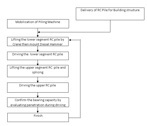
General flow chart for the piling works:
Pile Material:
PHC Spun Pile 600mm dia.
PHC Spun Pile 500mm dia.
RC Square Pile 400mm x 400mm
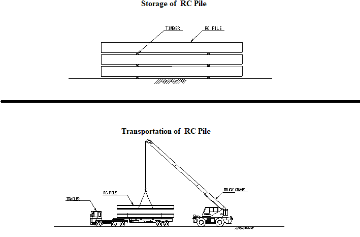
Piles will be plant fabricated and transported to the site by Barge and trailer truck. They will be supported by bedding timbers placed directly under the positions of lifting hoops.
Piles will be stored carefully on flat ground within the temporary yard. Piles will be stacked on top of one another to a maximum of three layer.
Material delivery dockets, receipts and inspection shall be conducted to every pile delivery at site. Result of the inspection and delivery documents shall be submitted to the Engineer.
Piling Equipment:
The following equipment shall be used for the Piling work.
Hammer: Diesel Hammer 4.5 – 7 tons class, (KOBELKO K45/KB60)
Base Machine: HITACHI PD9 or equivalent
Service Crane: 35 ton class, crane truck
Others: Semi-automatic welding machine / Oxy Acetylene cutting outfit
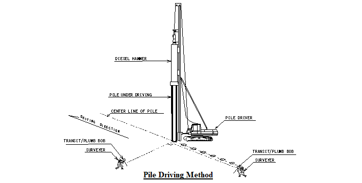
Piling by diesel hammer : ( Refer drawing below )
The pile will be driven by diesel hammer and driving shall stop when the bearing capacity is already reached and confirmed.
All piles shall be driven to their specified bearing capacity and location complying with technical specification and design drawings.
Driving Lower Segment Pile
Crane will lift up the lower segment pile. After lifting , the pile shall be held along leader of diesel hammer.
The pile position shall be adjusted by moving the leader. The hammer with the cap is then mounted on the pile top.
Before starting driving, the verticality and position of the pile is carefully checked by total station and theodolite and adjusted as required.
Driving Upper Segment Pile
When the lower segment had been driven the second segment will be positioned concentric to the bottom segment held up and aligned vertically.
Prior to splicing area to be jointed must be free from rust, oil, water and other foreign matter that would affect the quality of the welded joints. Splices will be by butt type joint using arc welding. All welded joints will be inspected visually.
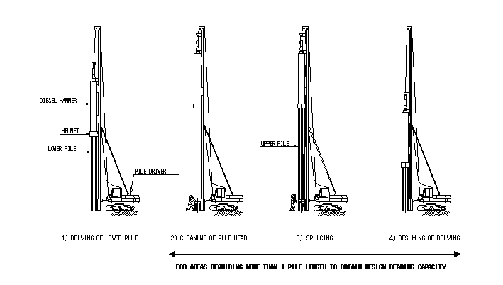
Driving will be stopped when bearing capacity is already achieved, through the application of Hiley’ s formula in calculating the bearing capacity. See PDA Test calculation.
If it is found that the bearing capacity is insufficient against design after the rebound record, the pile will be extended and re-driven until the bearing capacity is attained.
Ru = 9.81 (Ef. MR. H) x MR + e2.MP
S+0.5(C1+C2+C3) MR + MP
In which:
Ru: Ultimate Resistance, KN
MR: Weight of ram, Kg
H: Drop height of hammer, mm
Ef: Efficiency of fall of hammer
MP: Weight of pile + helmet , Kg
e: Coefficient of restitution
C1: Elastic deformation of pile , mm
C2: Elastic deformation of ground , mm
C3: Elastic deformation of pile head cushion , mm (here C3 = 2 mm).
S: average penetration, in mm per blow for at least the last 10 blows
(Use rebound record)
The result of Pile driving and bearing capacity shall be confirmed by consulting engineer. The records of pile installation shall be submitted to the engineer.
In case the pile tip can not reach the design level due to unforeseen hard layer, these matter will be reported to Engineer.
If piles can not be driven to the design level but has already attained the required bearing, the driving shall be stopped to avoid buckling or cracking in accordance with Specification and Engineer Instruction.
Pile head treatment shall be done after getting the Engineers’ Approval.
Pile Record
Before final setting of the piles, the rebound shall be recorded.
The pile driving is deemed completed after confirmation of the sufficient bearing capacity against design. Bearing capacity for all piles will be calculated with formulas.
Test Pile – (Test pile position refer to figure for pile driving)
Before piling, Pile Dynamic Analysis will be conducted to confirm the pile capacities and to decide the correction factor of Hiley’s formula. PDA test provides more information, about Skin resistance distribution, Toe resistance, simulated static load-settlement relationship, pile integrity, stresses in the pile during the blow.
The detail procedure shall be submitted in separate document.
Quality Control and Inspection of pile
Pile material such as concrete , rebar and wire strands or tendons ( for pre – stress type ) shall be inspected on factory before fabrication and the finished product shall be inspected before delivery.
The inspection report shall be received before arrival of piles on site.
Upon arrival on site, piles shall be inspected as to dimensions, quantity, and physical condition and reported to the consultant engineer.
Inspection prior to Welding Work
Prior to the welding, the grooved face and its adjacent areas shall be completely free from oil, paint, oxides, water and all other foreign materials.
When two lengths of pile are jointed, the end plates shall bear even in all areas, The welding must be carried out according to the manufacture’s instruction and must be checked before driving resumes.
During driving, the pile head will be protected by helmet of cast steel or mild steel fitted closely around the pile.
Packing (cushion) timber, covering the head of pile, will be placed on the pile and will be replaced as often as necessary to prevent damage to the piles.
Driving records.
- Program and progress
- The date and time of pile driving
- Position of the pile number and size of pile
- Type and size of hammer and for drop or single acting hammer , details of release mechanism ,the length of the drop or stroke, for diesel hammer the length of stroke and the blows per minute ; for double acting hammers the number of blows per minute and for automatic hydraulic drop hammers the recorded average energy per blow during an increment of penetration.
- Deviation from tolerance and the line and level shown on the drawings.
- L of toe of pile with hammer in place before driving.
- L. of toe of pile on completion of driving.
- Length of the completed pile and level of splices.
- Driving Log (Depth , blow counts per 200mm for whole of penetration , with times of interruption of breaks in driving ).
- The record of temporary compression for each of the last ten blows.
- Dolly and packing type and condition before and after driving.
- Details, date and time of any re-driving or testing.
Reinforcement Work
Manufacturer of reinforcing bar shall be proposed to the Engineer for accreditation and approval. No deliveries shall be accepted for use without decision by the engineer.
Every delivery of reinforcing bar supply for construction, the quantity and physical properties shall be checked by the Contractor. The quality shall be confirmed by checking mill certificate issued by the manufacturer through the comparison of the laboratory test result of specimen taken from the different kinds of diameter in the delivered product.
Material: Round bar & deformed bar shall be 2100 Kg/cm²- (Yield strength)
Reinforcement storage before fabrication
Reinforcement will be stored in a warehouse area at site with adequate protection from getting rusty, or protected from any element that would affect its quality condition as specified.
Storing will be organized by category, type, grade and diameter. As a rule, the end of each bar had been painted to differentiate the different grades.
Reinforcing steel that are rejected have to be stored in a separate place away from where it was accepted, before sending back to the supplier.
Reinforcement Fabrication Process
Workers will fabricate the bar according to the information mentioned on the label, and fabricated bars will be stored systematically according to their structural usage per work unit mentioned on their label (Work Unit, structure, drawing, category, type, diameter, grade…).
All precautions will be taken to avoid damage and bending the steel bars during storage, loading and transportation to the site. The bars should be protected from the rust by storage on wooden platform, crates or elevated trestles.
Installation at Site
The reinforcement installation will be in accordance with the drawings, the General Technical Specifications, and the Owner requirements (cover, spacer blocks, reinforcement continuity and tolerances).
Before any pouring, all the reinforcement shall be inspected and accepted by the Engineer or the owner’s representative.
The foreman on site will correct any deviation out of tolerances immediately upon notice before filling the inspection request.
FormWork Construction Procedure
Formwork Set-Up:
Blinding concrete shall be installed prior to placing formwork.
Form made of plywood or steel shall be cleaned on all its surfaces in contact with concrete shall be treated or painted with oil prior to the installation. Installation shall be made precisely on the lines and grades using string, spirit level, survey instrument etc.
Forms shall be kept firmly in position by putting tie rods or external support. Tie rods support shall be so arranged and distributed and strong enough to withstand the pressure during casting concrete.
Construction method
- Foundations shall be constructed first and then columns to the tripod beam bottom level. In the Workshop building, sub-columns and sub-beams system on wall, beam surface form will be done after the installation of steel framework.
- Establish accurate centerline axis and level for the layout of foundations, columns, beams, and floors, before installing forms.
- Form should be adequately supported or braced to avoid movements or displacement during casting concrete. Bolt connector or any acceptable pre fabricated support system is essential.
- Check the alignment of formwork by stretching a cord along edges of installed forms
- For additional supports, Iron and tension cable can be used as supports in the installation of forms of column footings. Check the establish centerline for accuracy to avoid deviations.
- Staging and scaffolding support system is to be utilized for beams and slab forms, and they are installed at the same time. During installation regular checking of lines and grades shall be made to ensure the evenness and straightness of slabs and beams during construction.
- position Steel and wood joist supports and bracings is utilized for forms of concrete structures. Jacks are installed at top and base of supports for adjusting height or length, all bases of support should be propped by a piece of wooden material to prevent settlement.
- All supporting columns and bracings should be anchored, hold and connect together to become stable frame system to secure structures during concreting.
Concrete Works
The class of concrete for each section of the works shall comply with Specification and applicable ASTM Standards.
|
Property |
Concrete Type |
||
|
1. Concrete Class |
D | E | G |
|
2. Application |
Over 2 Story Buildings | 1 Story Buildings |
Lean Concrete |
|
3. Cement Type-1 |
PCB40 | PCB40 |
PCB40 |
|
4. Water Cement Ratio |
0.475 | 0.5 |
.76 |
|
5. Minimum Cement Content (kg/m3) |
350 | 330 |
220 |
|
6. Max Aggregate Size |
19 | 19 |
38 |
| 7. Concrete Cylinder Strength at 28 days– Fc’ (Mpa) | 30Mpa | 25Mpa |
14Mpa |
Design mix shall be submitted and approved by the engineer and trial mix shall be conducted to confirm the compression strength and satisfy the specification.
In general, concrete must be casted within 60 minutes from mixing to placing. The concrete temperature shall be below 35⁰C as specified at the point of pouring. Other measures to keep the concrete temperature low is to keep the aggregates and water cool, or arrange early morning pouring to avoid casting daytime which has high humidity condition.
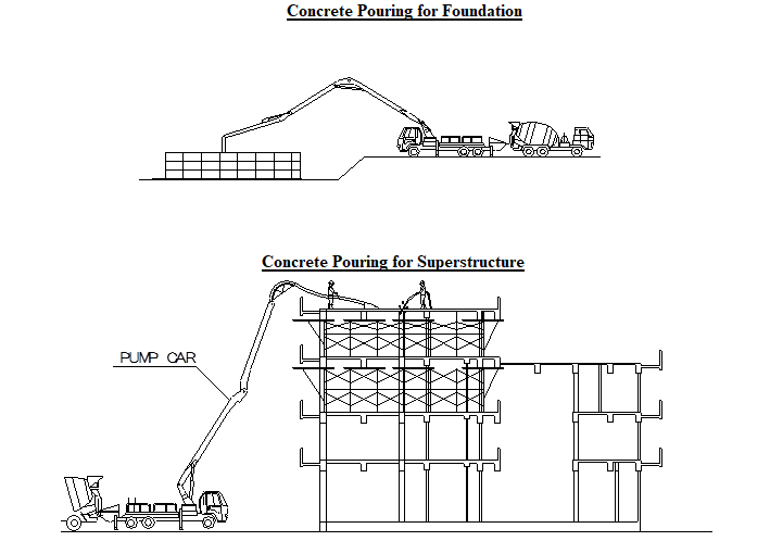
Construction method:
Concrete Pouring and Treatment requirements:
Do not change position, bend shape of reinforcement, position of formwork and thickness of concrete cover.
Also do not use vibrator to displace horizontally the concrete mix.
Concrete shall be poured continuously up to finish grade or construction joints indicated on the drawing shall be followed when there is a tendency to stop pouring.
Tremie pipe shall be utilized when pouring concrete beyond manual reach or above ground to avoid segregation of the ready mix concrete during pouring and maximum falling height be 1.5m.
Use concrete spacer between formwork and reinforcement to avoid displacement of reinforcement during concrete placement.
Concrete shall be continuously poured until one component is finished to avoid cold joints.
Structural components such as column, wall which is higher than 1.5m shall be provided with openings at 1.5m maximum vertical spacing to avoid concrete from segregation during pouring and to abide by the standard height of pour of 1.5 meters .
Use concrete vibrator to compact mix, vibration time shall be from 20 to 30 seconds. Use trowel to level the concrete surface.
If the concreting is too large in quantity that one time pouring is impossible, the contractor shall provide proper construction joints in accordance with the specification. These joints shall be located at places that have minimum effect of moment and shear, usually located at 1/3 or 2/3 points of the span of the structure or refer to the specifications on construction joints. Before casting the remaining portion roughened surface to ensure bonding with new concrete.
Concrete shall be poured in layers from 20-30cm then vibrate in accordance with the specified time. Number of vibrator depends on the concreting area, at least 3 stand-by vibrators in every concreting location as back up for conked out units.
Concrete for slab shall be leveled right after pouring. Pre cast concrete pieces for level control points shall be provided and removed before casted concrete gets hard.
Concrete Curing: 24 hours after Casting
All concrete shall be cured by either spraying water directly or spraying water on a mat placed on the concrete surface.
Water curing by sprinkling process, shall be repeated whenever the water dries up and maintain the concrete wet for a period of 7 days.
Concrete Finishing: Upon removing formworks, concrete surface shall be finished, repaired of any defects to ensure evenness and uniformity in color. All concrete surfaces shall be free from any irregularities. A waterproofing coat may also be applied to a selected location as specified.
Testing and Check for Acceptance: Concrete specimens for strength test shall be obtained in every 20 m³ batch group, and taken at the same time and place. Test sample standard dimensions are Ø=150mm x h= 300mm cylinder.
Masonry Works
Material Sample and technical data’s of hollow brick shall be submitted to the consultant for approval.
Bricks between column and lintel supports shall be arranged in accordance with the specification and drawings.
The mortar composition is the mixture of cement, sand and water by correct proportion specified.
For volume 3 : 5 : 1, for reinforced block work and elsewhere.
The mixing and kneading is to be done by manual mixing or a small a portable mixer.
Adequate and sufficient application of mortar for horizontal joints shall be applied, and bricks shall be wetted before laying.
The mortar for vertical joints shall be filled up by trowel during block laying and the ends of the brick must be “buttered” to enhance firm connection.
Excess mortar that came out on the surface shall be scrape out with a trowel. All horizontal and vertical joints shall have full mortar coverage.
The mortar squeezed from the joints shall be flushed with the the adjoining installed bricks.
Finish joints to face work after mortar has begun to stiffen by square raking. Follow specified standard for the maximum layer of bricks installation per day.
Masonry Work Preparation
- After removing formwork of slab, floor cleaning shall be done for marking.
- Survey group shall re-establish center line, ink marks shall be applied to a re-located margin lines of brick walls on columns and slabs.
- Adjust deviated anchor bars that will connect to brick walls .
- Mobilize bricks, cement, mortar, water, scaffolding to construction area.
Masonry Construction order:
Brick work shall be constructed from bottom to top process, main walls shall be laid first followed by partition walls.
Boundary walls shall be built first followed by partition wall.
Check regularly the verticality and straightness during brick laying by ruler and plumb.
Stretched cord to both ends to ensure brick laying course are in straight line.
Structural Steel & Roofing Work
Manufacturer of steel materials shall be proposed to the engineer for approval prior to procurement and delivery.
All steel materials delivered to the fabrication shop, shall be inspected and checked by the recipient.
Delivery dockets, mill certificates, quantity and physical property checking of the material shall be performed before unloading.
Inferior and sub standard materials are rejected and prevented from unloading. The material technical data’s from the mill certificate shall be confirmed by conducting laboratory test on sample taken from the delivered materials. Usage of the material depends on the test result for the specified stress requirements.
Shop Fabrication
Prior to fabrication, shop drawings shall be submitted to the engineer for approval. Bended steel members shall conform to the approved shop drawing. In order to maintain quality and minimize the installation and assembly period, painting must be done in the fabrication yard.
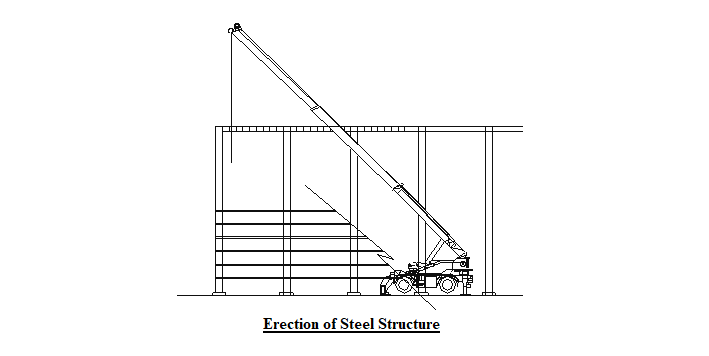
Erection Work
Detailed erection sequence for each structure approved by the Engineer shall be acquired prior to erection. Mobile cranes will be used for the erection.
Temporary bracings shall be prepared before column erection in order to maintain the verticality and alignment.
After checking proper alignment, fasten these steel members by connectors of high strength bolt and tighten it according to its specified torque moment requirement by using torque wrench or special tightening hand tool.
Touch up paint will be applied to all scratched surfaces to restore its required texture surfaces.
Metal Roofing and Cladding Work
The material for metal roofing and cladding, including shop drawing requirement for this work shall be submitted to Engineer for approval. The material shall be fabricated based on the approved shop drawings submitted to the manufacturer.
Basic Steps for installation of metal roofing and cladding is explained below.
Step 1: Establish the grids and elevations based on the standard procedure in executing this work item or relevant acceptable method through markings using stretched string or wire along its grid or elevation.
Step 2: Fixing metal sheets onto purlin and girt using self-tapping screws.
Step 3: Sealant shall be applied at proper wrapped portion based on the manufacturer’s shop drawing
Step 4: Fix flashings, trims, gutters, down spout pipes and louvers.
Roofing Work:
Roofing material and shop drawing for this type of work shall be submitted to the engineer for approval.
Installation procedure shall conform to manufacturer’s product technical specification on installation. Precautions against accident shall be well considered for its sensitiveness in executing this work.
Before placing waterproofing membrane, the surface shall be thoroughly cleaned and primer paint shall be applied in dry condition. Apply waterproofing membrane on primer coated surface, by pre heating to adhere firmly. Overlapping portion of waterproofing membrane shall be carefully bonded with each other to avoid water leakage.
Occupational Health And Safety Control for Steel Structure Work.
Everybody who will carry out the works shall use all the necessary protective or safety gears and abide by the occupational health and safety control plan of the project to avoid the occurrence of accident and minimize the potential cause of hazard.
Working areas shall be provided with warning devices signage’s or barriers , and frequently checked by Safety Engineer during work time.
Ensure all vehicles and equipment is safe and fully efficient, guarded and equipped with safety devices and has been subjected to necessary test.
Make sure that operators, drivers and attendants will only concern themselves on the equipment for which they have been thoroughly trained.
Check working efficiency of equipment for its intended purpose, and its valid registration and calibration certificates.
Safety lifelines shall be provided to all elevated work areas to enhance connection point safety harness or belts used by workers, especially to a location where scaffolding impossible.
All workers working higher than 1.5 meters must wear a safety harness or belt. The safety line manufacturer’s recommendations for use shall be strictly followed.
Finishing Works
Door & Window Works
Doors, louvers and windows shall be of the approved ones and in compliance with the specification. Installations shall be made in accordance with the schedule to keep finishing work in sequence and to avoid lapping of activities that cause delay or damage impact to other finishing work.
Installed doors, louvers and windows shall be keep protected to avoid damages caused by other ongoing finishing works and other parties.
Plastering
The thickness and mix proportion of mortar for plastering or rendering shall be in accordance with the specification and the mixing and kneading process is to be done manually or by portable mixer.
Cement shall be of the standard ordinary Portland cement and sand, sourced out from land or river and shall be approved by the Engineer.
Tiling
Tile material and shop drawing for tile layout or arrangement shall be submitted to engineer for approval. Prior to tile laying concrete surface where tile is laid shall be cleaned, free from dust, oil, grease and other elements that would affect quality of tile bed mortar.
Bed mortar of specified mix proportion (1:3) is placed and spread evenly with a minimum thickness of 10mm over the area to be tiled. Tiles are then laid over the evenly applied bed mortar until it adhere firmly in place.
Tile gaps shall be filled up with grout of approved type or as specified in the plan. After grouting tiled area shall be cleaned from excess grout to keep the work clean as specified.
Painting
Paint material shall be of the approved one in accordance with specification. Surface preparation before painting shall conform to the manufacturer’s instruction to each kind of paint material.
Number of coat, dry film thickness shall comply with the approved paint schedule. Where required, final coat shall be carried out, after or almost all of the work nearby is completed to minimize damage.
Ceiling Work
The material for ceiling work shall be submitted to the engineer for approval. Shop drawing for ceiling layout and arrangement plan shall be approved by the consultant. And proper coordination to MEP works shall be made to avoid lapping of works that cause delay in executing the work.
Hangers shall be installed, fastened and fixed properly under the concrete slab or steel structural members. Then thin gauge and light steel frame is installed to enhance level adjustments’ required. MEP works above ceiling shall be completed before installing the ceiling frame.
Deflections or damage on the T-runner frame shall be repaired prior to installation of the gypsum board.
Mechanical Electrical & Plumbing Work
Air Conditioning and Ventilation Work
Air Conditioning and Ventilation system including shop drawing plans and all schematic layouts for these works shall be submitted to the Engineer for approval.
All slots in exterior walls intended for pipe crossing shall be made impervious. Shop drawings of ceilings and walls shall reflect location of air conditioner, ventilator and ducts, to account for the balance distribution of other equipment.
Installation of air conditioner, ventilator, air inlet and outlet, including pipes, ducts and other related fittings shall conform as indicated in the shop drawings. Exhaust pipe/duct shall sloped downward from inside to outside.
Plumbing Work
Material and equipment for Plumbing work and shop drawings shall be submitted to the engineer for approval.
Excavation and trenching of soil, preparation of sleeves on floor, wall and beam where there are necessary in structures shall be well considered.
Before being installed, all pipes shall be thoroughly cleaned, free from any scales, burrs, rusts and obstructions.
Prefabrication, installation and jointing of pipes (including fittings) with adhesive for PVC material, including valves, strainers, and flexible joints shall be done carefully.
Adequate pipe supports, hanging steel bars and anchorage shall be provided.
Sealing of pipe sleeves shall be done properly.
Pressure test for water supply pipes and flushing test for drainage pipes shall be performed.
Back-fill and compaction of soil for underground piping shall be done carefully.
Electrical Work
Material and equipment for electrical work and shop drawings shall be submitted to the Engineer for approval.
Preparation for efficient wire or cable laying such as confirmation of the exact locations where they are to be laid, cleaning the trenches or ducts, scraping/brushing inside of the duct bank, pipes or conduits and so on shall be done.
All cable connections shall be made inside distribution board; pull box and outlet box etc. and the connection shall never be exposed or inside of conduits.
Cable alignment, binding, fixing, wall penetration sealing, cable marking, cable penetration into conduits between cable trays, ducts and Job-site junction boxes and similar shall be made properly.
Adequate press-save coupling, wire connector or press combine terminal etc. will be used as a principle for the connection of wires and/or cables.
In the case of line pipe exceeding 30m for one section or where leading in is difficult, pull box shall be used.
Fixing method of distribution boards etc. shall be specified on the construction drawing, and shall be fixed accordingly.
The position of lighting apparatus shall be indicated on ceiling allotted sketch in advance, taking balance with other facilities apparatus.
Fixing height of switch and socket outlet shall be shown on the shop drawing securing the approval of the consultant and shall be fixed accordingly.
Testing and Trial Run
After installation of Mechanical and Electrical equipment, test and inspection including their record reports will be done. Trial operation shall be proceeded to adjust and check the function of equipment.
Discover more from Project Management 123
Subscribe to get the latest posts sent to your email.