This article covers the design of connections and the fabrication, supply and erection of structural steel work, roofing system, wall cladding and steel decking. Below is a list of applicable standards and codes:
- BS 7668:1994, BS EN 10113, BS EN 10155, BS EN 10210; grade 43C: Structural Steel including sections facricated from steel
- BS4: Structural steel sections. Part 1 ‑ Hot rolled sections
- BS4848: Steel Angles equal and unequal legs
- BS1449: Cold Rolled Steel Sections
- BS1449: Part 1 Carbon steel plate, sheet and strip
- BS3692: ISO metric precision hexagon bolts, screws and nuts
- BS4190: ISO metric black hexagon bolts, screws and nuts
- BS4320: Metal washers for general engineering purposes
- BS7613 & BS7668: Weldable structural steels
- BS4395: High strength friction grip bolts and associated nuts and washers for structural engineering.
- BS4848: Hot rolled structural steel sections.
- BS10210, BS6323 and BS1387: Steel tubes and pipes
- BS970 or AISI 316: Stainless Steel Sections
- BS EN/301:1997: alloy HE9 with the mechanical properties of the WP condition, BS1161, 1471 and 1474, Anodised finish to BS1615 (general) and BS3987 (exterior work): Aluminium extrusions
- BS EN 485, BS EN 515, BS 573 alloy NS4-H6 ( hard) Aluminium sheet
- MIP-P-6883A and BS6949: Bituminous Paint
- BS 729: Galvanizing
Design of connections
Loadings are to be based on the following design criteria:
- Earthquake: Zone 2A(Uniform Building Code 1997)
- Wind Speed: 45m/sec
- Roofs: In accordance with Table 23 C of the Uniform Building Code 1997
The Contractor shall show in his calculations, submitted in accordance with the submittals, the values of the axial forces, shear forces and bending moments to be accommodated. The Contractor shall design and detail all connections in accordance with BS449 Part 2 and the relevant British Standards referred to therein. Shop connections shall be bolted or welded but Site connections shall be bolted. Bolts complying with BS 3692 or BS 4190 shall be of strength grade 4.6, 6.9, 8.8 or 10.9 and washers complying with BS4320 used with such bolts shall be tapered or flat, as appropriate, to ensure full bearing for the nuts and the bolt heads. If bolts complying with BS 3692 or BS 4190 are used in Site connections, all bolts in any one connection shall be of the same diameter and all bolts used on Site shall be of the same strength grade, except where otherwise instructed by the consultant. High strength friction grip bolts, nuts and washers shall be installed in accordance with BS4604 Parts 1 and 2.
Types and grades of steel to be used
Materials generally shall comply with B.S.449, BS7613 and BS7668 and other relevant British Standards referred to therein. Steelwork generally shall be grade 43 or grade 50.
- Steels of grades 43A and B complying with BS7613 and BS7668 shall not be used in thickness over 40mm.
- Steel of grades 50B complying with BS 7613 and BS 7668 shall not be used for universal beams, plates, universal plates and normalised flats in thickness over 40mm. In cases of universal columns and other sections the maximum thickness shall be 20mm.
- Steels of grades 43C, D and E, 50C and complying with BS 7613 and BS 7668 may be used up to the thickness shown below:
Grade Plates Section etc.
- 43C 50mm 50mm
- 43D 75mm 50mm
- 43E 75mm 50mm
- 50C 75mm 40mm or 75mm in normalized condition
For thicknesses over those specified the impact test requirement shall be not less than 27J at 0 degrees C. All steel sections and plates exceeding 40mm thickness, and subject to tensile forces acting perpendicular to the section or plates, are to be tested for lamination. Tubular sections shall be completely sealed. For additional technical guidance reference shall be made to the ‘R.H.S. Guide to Fabrication and Design’ published by the British Steel Corporation Tubes Division.
Fabrication and Workmanship Requirements
Steelworks shall be fabricated to comply with BS449:Part 2 and with the following further requirements: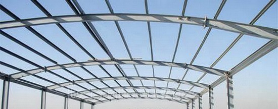
- All members shall be accurately cut square or to the required angle and neatly dressed
- Flanges shall be neatly cut away or notched where required. Notches shall be as small as possible and shall be curved in the inner corner
- Sheared or cropped edges shall be dressed to a neat finish and shall be free from distortion
- Flame cutting shall be by machine and edges shall be dressed to give a smooth and uniform surface
- All holes shall be drilled. The diameter of holes for high tensile or high strength friction grip bolts shall not exceed the diameter of the bolt by more than 1.5mm. Holes found out of alignment shall be corrected by reaming and, if necessary, oversize bolts shall be provided.
- Bearing stiffeners shall be ground to fit accurately and shall be in contact over 90% of the stiffener area unless welds, designed to transmit the full reaction of the load between stiffener and flange, are provided.
- Butt joints transmitting compressive stresses in bearing shall be in contact over an area not less than 75% of the abutting faces, the contact area being generally symmetrical about the major and minor axes. All base plates, cap ends and column ends bearing against base plates, shall be milled.
- All steelwork shall be handled with cranes. Dragging, skidding etc. will not be permitted at any time.
Welding of Steel Members
Welded fabrication shall be carried out by metal arc welding. All welding procedures, weld testing and proficiency testing of welders shall comply with the appropriate British Standards listed below for the grades and thicknesses of steel and the types of weld specified:
- BS EN ISO 2560 : 2005 Covered electrodes for manual metal arc welding of mild steel and medium tensile steel
- BS2600Methods of radiographic examination of fusion welded butt joints in steel
- BS3923 Methods for ultrasonic examination of welds Part 1. Manual examination of fusion welds in ferritic steel
- BS4165 Electrode wires and fluxes for the submerged arc welding of carbon steel and medium tensile steel
- BS EN 288 Approval of welding procedures. Part 1 Fusion welding of steel
- BS EN 287 Approval testing of welders working to approved welding procedures. Part 1 Fusion welding of steel
- BS4872 Approval testing of welders when welding procedure approval is not required. Part 1 Fusion welding of steel
- BS5135 Metal arc welding of carbon and carbon manganese steels
- BS 3019 Welding in stainless steel
- BS5289 Visual Inspection of fusion welded joints.
Welding shall be carried out in workshops under the specified conditions of temperature, etc., and where continuous supervision is exercised. Site welding will only be permitted where authorised by the consultant. Intermittent welds will not be permitted. Only certificated welders shall be used in fabricating the Works and their proficiency shall be tested in accordance with this Clause before they carry out any fabrication.
The consultant reserves the right to have any welding operator re tested at any time during the Contract. The Contractor shall include in his Tender for the cost of the testing of his operators, including all additional labour, material and apparatus and for the cost of providing the test plates and facilities for testing.
The sequence of welding operations shall be arranged to minimize distortions and residual stress during fabrication and in the structure after erection. Radio graphic and ultrasonic testing of welds shall be carried out as instructed by the consultant. Welds shall comply with the acceptance criteria set out in Section 8 of the Code published by the American Welding Society, ANSI/AWS D1.1.81, Design of New Buildings.
Any weld which is found to be unacceptable shall be ground out and re welded. Such grinding shall be done with a tapering transition from the unacceptable to the acceptable part of the weld. In addition to radio graphic and ultrasonic testing, the Contractor shall have available, in the fabrication shop, equipment and materials for dye penetrant and magnetic crack detection tests and shall apply such tests when instructed by the consultant. Preheating of members before welding shall be carried out in accordance with BS5135.
Type and extent of weld testing to be carried out
The Contractor shall, at his own expense, make such tests on materials as may be required by the consultant, in the manner described in BS EN 10 002-1:1990 and BS 7613 and BS 7668, and he shall notify the consultant in good time to enable his Representative to be present when the tests are carried out.
The Contractor shall supply rolling mill test certificates covering all the steel used in the Works, including tests for each rolling. The Contractor shall give the consultant all facilities to inspect the steelwork at his Works during fabrication and assembly. All work rejected shall be corrected or replaced, as necessary, at the Contractor’s own expense and to the satisfaction of the consultant. The Contractor shall provide the equipment and facilities for carrying out non destructive tests of welds.
Bolts Requirements
Bolt holes shall be accurately aligned so that bolts can be inserted without force. Bolts shall not be driven home and drift pins used to draw members into alignment shall not be used in a manner likely to distort or enlarge bolt holes. Bolts shall be of sufficient length to show at least two clear threads beyond the nut when fully tightened.
When bolts are used in bearing, members shall not bear on the threaded part. Joint interfaces shall be clean and free from loose scale, loose rust, oil, grease, paint and all other deleterious matter before the joint is assembled, unless otherwise instructed. All bolts shall be provided with washers under the nuts. Tapered washers shall be provided on the insides of the flanges of rolled steel joists and channels. High strength friction grip bolts shall be provided with their special washers under both head and nut. Where bolts are used in the vertical or inclined positions, the bolts shall face downwards. All bolts, nuts and washers are to be painted for protection against corrosion.
Alternative methods of protection will be subject to the consultant’s approval. High strength friction grip bolts shall comply with the following requirements: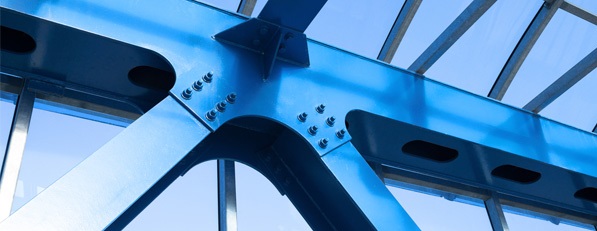
- non load indicating connectors shall be installed in accordance with BS4604 Parts 1 and 2.
- load indicating connectors shall be installed in accordance with the manufacturer’s recommendations but the minimum shank tension shall be in accordance with BS4604 Parts 1 and 2
- the Contractor shall demonstrate, on Site, to the satisfaction of the consultant, by means of sample bolts and a calibrated bolt load meter, that the minimum shank tension is obtained with the type of fastener chosen and the equipment he proposes to use for tightening.
High strength friction grip bolts which have been tightened and subsequently released shall not be used in the Works. All HSFG bolts shall be tightened with torque spanners. When the Contractor has installed HSFG bolts ready for inspection by the consultant the bolts shall be painted with paint color A; when the consultant has inspected the installation, is entirely satisfied and has given his approval in writing the bolts shall be painted with paint color B. The consultant will choose colors A and B so as to be easily recognizable from a distance.
Fabrication Tolerances
Fabricated steel members shall comply with the dimensions and shapes shown on the drawings and the accepted shop drawings within the tolerances set out below:
- Straightness: Compression Members shall not deviate from straightness by more than 1/1000 of the axial length between points of restraint. Other members shall not deviate from straightness by more than 1/1000 of the axial length.
- Width and depth: Plus or minus 3.0 mm
- Length: Plus or minus 2.0 mm
- Machined end faces: No part of any machined end face of a member other than a column shall deviate from a plane at right angles to the axis of the member by more than 0.5 mm
- No part of the machined bearing face of a column shall deviate from a plane at right angles to the axis of the column by more than 0.25 mm and 90 per cent of the bearing area shall have full contact uniformly distributed over the whole of the area and substantially symmetrical about the major and minor axes.
- Built up members:
a. The centre line of a web shall not deviate by more than 6.0 mm from the plane passing through the centre lines of the flanges.
b. A web without intermediate stiffener shall not deviate from the plane representing the true centreline of the web by more than the depth of the web divided by 150.
c. A web having intermediate stiffeners shall not deviate from the plane representing the true centreline of the web by more than the amount stated below:
- for D/t less than 150, the least panel dimension divided by 100.
- for D/t greater than 150, the least panel dimension divided by 80,
- where D is the depth of the web and t is the thickness.
d. tilt on flanges of welded beams or girders shall not exceed 1/200 of the total flange width or 3 mm whichever is the greater. The measurement of the offset shall be at the toe of the flange from a line normal to the plane of the web through the intersection of the web centreline and the outside surface of the flange plate.
Erection of Steel Structure
Erection of steel work shall be carried out in a manner which will prevent damage of any kind to the steel work or to structures, finishes, services or other installations. The contractor shall be responsible for the stability of the structure at all stages during erection and shall provide, and remove on completion, any temporary bracings, guys and the like that may be required. Columns shall be set in position on steel wedges and packing.
Site connections shall not be fully tightened until sufficient of the structure has been plumbed, leveled and aligned to ensure completion of the remainder without any need to strain members into position. Bolted connections shall be made in accordance with the instructions given. On completion of erection; the structure shall be correct to line and level and shall not be out of plumb in any direction by more than 6.0 mm.
Connections to concrete: Bolted connections to concrete members shall be made using resin bonded fixings or steel expanding fixings of sufficient capacity to carry and sustain the applied loads. Pre drilled holes shall be of correct size and length to suit the loads and the bolts shall be entered, secured and tightened in accordance with the bolt manufacturer’s instructions.
Bedding and grouting: After the steelwork has been erected to the satisfaction of the consultant the holding down bolts shall be grouted and the space below the base-plates shall be filled with mortar, all in accordance with Specification Section 3300.
Protective Coatings
The method of cleaning and the protective coatings to be applied in the fabrication shop and/or on Site are stated in the following section.
Details of cleaning and protective coatings
Prior to fabrication the steel shall be shot blasted to Sa 2 1/2 finish as defined in the Swedish Standard SIS 55900. Within three hours of the completion of shot blasting, one coat of blast primer of poly-amide cured epoxy containing phosphate inhibitive pigment shall be applied to all surfaces, to a total dry film thickness of 25 microns.
After steel fabrication all surfaces shall be wire brushed and painted with one coat of the same primer, to give a DFT of 75 microns. Surfaces shall thereafter receive two coats of quick drying zinc phosphate epoxy resin type paint, to a total dry film thickness of 100 microns. Shop paintwork shall be carried out using priming paints from an approved manufacturer.
All contact surfaces for friction grip bolts at moment connections shall be absolutely clean, to the approval of the consultant, and shall be protected by bolting thereto pieces of clean sealed hardboard or plywood. The surfaces shall be kept free from contamination and the masking pieces shall remain in position until the joints are about to be made. Other contact surfaces shall be painted and shall be brought together whilst the final coat is still wet.
This Clause applies to surfaces brought together in the workshop during fabrication. Details of the proposed paint system, with manufacturer’s names and full specifications of the paints proposed shall be submitted to the consultant for approval and the work of cleaning, painting and fabrication shall not be commenced until the written approval to the paint system and materials has been obtained. Blasting, cleaning and painting shall be in accordance with the recommendations of Code of Practice CP 2008, or as herein modified, to the complete satisfaction of the consultant.
All operations shall be carried out under cover and in no case shall steelwork be left in the open after cleaning and painting. All paints shall be properly dried before steelwork is dispatched from the place of fabrication. The Contractor shall ensure that the methods of packing for shipping and transport are adequate to protect the welded parts and painted surfaces from damage occurring during handling, shipping, transporting and off loading at Site. The Contractor shall burn off any existing paint before site welding, with oxy acetylene or similar flame torches.
Painting of steelwork
All structural steelwork shall be painted with the following painting system immediately after blast cleaning to SA2.5.
- Blast Primer – Polyamide cured epoxy containing phosphate : 25 microns
- Primer Coat -Polyamide cured epoxy containing phosphate : 75 microns
- Intermediate Coat – Zinc Phosphate epoxy resin :100 microns
- Finishing Coat-Two pack polyurethane : 75 microns
TOTAL DFT :275 microns
Painting for fire resistance
All steel beams and columns are to be fire-protected by an intumescent paint system to give a 2 – hour fire protection. The steel surfaces are to be grit-blasted to SA 21/2 and coated with a protective priming coat of a single pack high build zinc phosphate primer to a DFT of 75 microns. The intumescent base coat is to be followed by a top sealer in accordance with the manufacturer’s written instructions to give the required 2-hours fire protection. The top seal shall have a satin finish with color to match the main steel work.
Protective treatment for bolts, nuts and washers: All bolts, nuts and washers to be used, as permanent connections in the Works shall be galvanized.
Galvanizing Requirements: All steel described to be galvanized shall be hot dip galvanized in accordance with BS729 or ISO R1459, 1460 and 1461. The coating of zinc shall not be less than specified in these standards. Galvanizing shall be carried out after drilling, welding, trimming are completed and fittings added. All galvanized surfaces shall present a bright surface having a crystalline structure, clean and free from drops of spatter or treacly edges. Prior to galvanizing, holes and threads in nuts, etc. shall be cut oversize to allow for the thickness of zinc on bolts and the holes and threads.
Discover more from Project Management 123
Subscribe to get the latest posts sent to your email.