The purpose of this method statement is to define the procedure for the preparation of pile caps before starting of the waterproofing and the pile head treatment.
The sequence of work shall be Piling , Dewatering, Excavation to remove the soil and pile breaking.
Roles and responsibilities:
Project Manager
Ensuring that the project works in his zone are carried out in accordance with company policies and in accordance with the requirements of the quality requirements.
Ensuring the full compliance of subcontractors with company quality policies and with the requirements of the project quality plan.
To ensure that all the equipment required to execute the works according to the construction program are available, in good condition, and provide any additional equipment that might be required.
To co-ordinate with the Construction Manager, Project Engineer, Safety Engineer, Foreman and Surveyor for a safe and proper execution of the works.
To guide specific attention to all safety measures in co-ordination with the safety officer/engineer.
Construction Manager
Ensure area is ready and safe to start the works.
Set up required equipment and plant through discussion with the Project Manager and Project Engineer/Works Supervisor.
Ensure the works are carried out according to the specification, quality and approved shop drawings.
Liaise and co-ordinate with the Project Manager for the agreed sequence of works with respect to the construction program.
Allocation of required manpower through co-ordination with the Project Manager.
Provide the risk assessments for the works in hand.
Provide sufficient and safe access for operatives, trucks and pumps.
Take precautionary measures with regards to protecting works from hot weather, wind, rain and sun.
Civil Project Engineer
The engineer shall carry out his duties in a manner that shall be coordinated by the project manager on a daily basis, and shall ensure proper distribution of the workforce and equipment at required locations.
To be aware of test frequencies related to the formation level.
To control disposal of waste excavated material according to the instructions received from the project manager.
To co-ordinate with the Safety Officer to maintain safe working and proper housekeeping of the site. To comply with the safety measures and ensure that all Safety Officer Teams are aware of the same to prevent accident and loss.
To monitor and check all activities and ensure that works shall be carried out according to specifications, quality and approved drawings.
To inform the QC Inspector of the areas ready for inspection.
QA/QC Engineer / Inspector
Ensuring that Consultant/Client inspection requests are implemented.
Compilation of all necessary quality control checklists
Assisting Consultants during the Inspections.
Coordinating with the third party lab regarding tests and results.
The control of work performance by means of checking the work before consultants’ inspection and issuing RFIs & punch lists as necessary.
Completion of documentation to verify the work performed.
Controlling all inspection activities on-site in line with ITPs.
Ensuring that all test equipment including surveying equipment is calibrated and is suitable for use on-site.
Surveyor
To establish benchmarks from agreed reference points, provide required setting out and level markings and follow up with regular checks.
Co-ordinate with the Project Engineer / Foreman and ensure the approved shop drawings/construction drawings shall be implemented properly.
Maintain survey details and reports, periodically check the progressing works and advise the project manager of any deviation from the drawings.
HSE Engineer/Officer
To ensure that all the persons involved in the works are aware of their responsibilities, and that they have enough understanding of the safety procedures.
The safety officer in co-ordination with the Project Manager shall ensure that all the implemented safety measures are effective enough to maintain safe working on the site.
To maintain continuous inspections of the site activities, advise and train persons on a daily basis to prevent accidents and personnel injury.
To give special concern to housekeeping, and ensure that the site is maintained clean and tidy.
To ensure all the relevant safety sign boards for different works are in place.
Foremen/ Works Supervisor
Ensure the works are progressed in the sequence as agreed with the Project Manager.
Liaise with the Project / Construction Manager for the allocation of the work force, ensuring adequate manpower is available.
Liaise with the site manager to ensure all the required plant / materials are available to construct the works.
Full time supervision shall be required to ensure the works are carried out in accordance to specifications, quality and approved drawings.
Equipment’s, Tools & Materials
- Earth moving Equipment
- Survey instruments
- Compactors
- Hand tools
- Black sand
- OPC
- Road Base
- Masonry Blocks
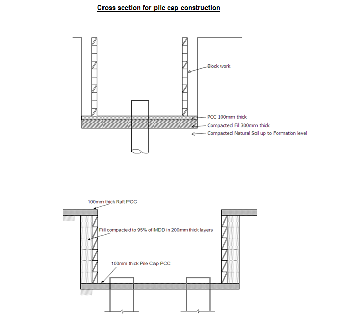
Pile Cap Works
Pile Caps Layout: The location of the pile caps shall be marked out by the surveyor in accordance with the approved shop drawings.
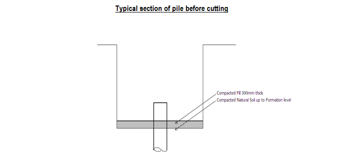
Excavation: The excavation work shall be started taking level readings to ensure that the level excavated does not exceed the required excavation depth.
The exposed formation level shall be well compacted and its density tested.
300mm Sub base filling: The excavation shall be back filled to the required level in a 300mm thick layer with sub-base material up to the PCC level in accordance to the approved shop drawings and compacted to 95% compaction.
Pile Repair :
At this point any defects observed in the concrete shall be repaired. This repair shall be apart from the pile head treatment.
The repair methodology submitted by piling contractor and approved by the Consulting Engineers shall be followed.
For minor concrete defect and broken edges, EMACO S23 NB and Sika Top Armatec 110 EpoCem shall be used. The concrete shall be cleaned off of dirt and unsound concrete.
The shuttering shall be fixed. The primer Sika Top Armatec 110 EpoCem shall be applied and after allowing it to cure for two hours the EMACO S23 NB epoxy concrete shall be cast.
All repair works shall be done in accordance with the manufacturer’s recommendations and the approved method statement.
Anti-Termite Treatment
The compacted area ready to receive concrete shall be treated with termicide as per the approved method statement of the applicator.
Once treatment is complete the area shall be covered by polythene sheet in accordance with the manufacturer’s recommendations.
Casting of PCC
Level tabs or level steel pegs shall fixed by the surveyor. Concrete shall be cast to the pegged level.
During the final finish concrete the levels shall be checked a final time.
Curing of PCC
Once the PCC has set curing shall be started and shall be maintained for 3 days.
Pile Head Treatment
The pile head treatment shall be done in accordance with the manufacturer’s recommendations and the applicator’s approved method statement.
Side Shutter Block work
Masonry block work shall be built at the perimeter of the pile cap. The surveyor shall layout the line of pile cap. Mortar of ratio 1:3 shall be used.
The mortar shall be hand mixed to give a homogeneous blend.
Care shall be taken in laying the blocks straight and in plumb.
Block wall’s inner face shall be finished to a smooth finish to receive the waterproofing.
Waterproofing
Along the perimeter of the pile head and the pile cap 50mmx50mm angle fillets shall be made using sand cement mortar.
The waterproofing system shall be applied in accordance with the manufacturer’s recommendations and the applicator’s approved method statement.
Backfilling
The area behind the block wall shall be backfilled in 250mm thick layers watered down and compacted to 95%.
During backfilling the termicide shall be sprayed after every 1 meter of backfilling.
RCC Works
The fixing of reinforcement steel and placement of concrete shall be done in a single cast with the raft.
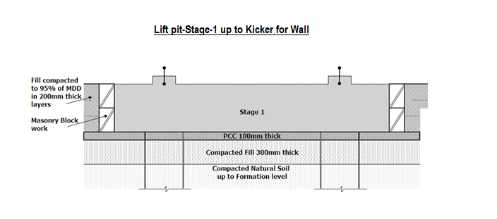
Lift Pit Construction
Construction of the lift pit shall be done in two stages.
Lift Pit Stage 1: foundation of the lift pit to the kicker
The foundation of the Lift Pit shall be constructed up the kicker of the pit wall.
The Stage 2 shall be the readying of the pit walls up to the bottom of the raft foundation.
Dewatering
No construction work or concreting shall be carried out unless an excavation is dry and shall be kept free from water till the concrete has sufficiently set so as not to be damaged due to percolating water.
A dewatering system shall be installed to maintain the water table level lower than the formation level.
Layout
The location of the pile caps shall be marked out by the surveyor in accordance with the approved shop drawings.
Excavation
The excavation work shall be started taking level readings to ensure that the level excavated does not exceed the required excavation depth.
The exposed formation level shall be well compacted and its density tested.
300mm Road base filling
The excavation shall be back filled to the required level in a 300mm thick road base layer up to the PCC level in accordance to the approved shop drawings and compacted to 95% compaction.
Pile Repair
At this point any defects observed in the concrete shall be repaired. The repair methodology approved by the Consulting Engineers shall be followed.
Anti-Termite Treatment
The compacted area ready to receive concrete shall be treated with termicide as per the approved method statement of the applicator.
Once treatment is complete the area shall be covered by polythene sheet in accordance with the manufacturer’s recommendations.
During backfilling the termicide shall be sprayed after every 1 meter of backfilling.
Casting of PCC
Level tabs or level steel pegs shall fixed by the surveyor. Concrete shall be cast to the pegged level.
During the final finish concrete the levels shall be checked a final time.
Once the concrete has set curing shall be started and shall be maintained for 3 days.
Side Shutter Block work
Masonry block work shall be built at the perimeter of the pile cap.
The surveyor shall layout the line of pile cap. Mortar of ratio 1:3 shall be used.
The mortar shall be hand mixed to give a homogeneous blend.
Care shall be taken in laying the blocks straight and in plumb.
Block wall’s inner face shall be finished to a smooth finish to receive the waterproofing.
Pile Head Treatment
The pile head treatment shall be done in accordance with the manufacturer’s recommendations and the applicator’s approved method statement.
Waterproofing
Along the perimeter of the pile head and the pile cap 50mm x 50mm angle fillets shall be made using sand cement mortar.
The waterproofing system shall be applied in accordance with the manufacturer’s recommendations and the applicator’s approved method statement.
Backfilling
The area behind the block wall shall be backfilled in 250mm thick layers watered down and compacted to 95%.
During backfilling the termicide shall be sprayed after every 1 meter of backfilling.
RCC Works Stage 1
The reinforcement steel for the pit foundation shall be fixed as per the latest approved shop drawing.
The concrete shall be cast taking care prevent vertical drops of more than 2m.
In case a vertical drop exceeds 2m a chute or trunking shall be used.
Curing
Once the concrete has set curing shall be started and shall be maintained for 7 days.
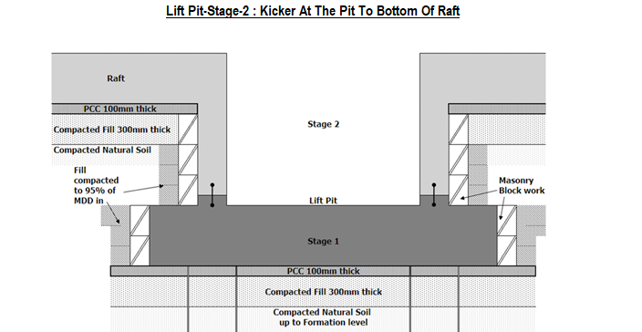
Lift Pit: Stage-2: Kicker to bottom of raft
Side Shutter Block work
The day after casting concrete layout for the block work shall begin.
The masonry block work shall be built at the perimeter of the lift pit to act as a permanent shutter.
The block work shall be built as described above.
Waterproofing
The water bar shall be cleaned and inspected for any damages.
The waterproofing system shall be applied in accordance with the manufacturer’s recommendations and the applicator’s approved waterproofing method statement.
Backfilling
The area behind the block wall shall be backfilled in 250mm thick layers watered down and compacted to 95%.
During backfilling the termicide shall be sprayed after every 1 meter of backfilling.
RCC Works Stage 2
The fixing of reinforcement steel and placement of concrete shall be done in a single cast with the raft.
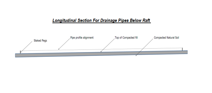
Drainage System Installation
The drainage system shall be installed below the raft foundation. It shall comprise of pipe fixing and manhole (catch basin) installation.
Pipe fixing
Layout
The alignment of the drainage pipes shall be marked out by the surveyor in accordance with the approved shop drawings.
Excavation
The excavation work shall be started taking level readings to ensure that the level excavated does not exceed the required excavation depth.
The excavation shall be leveled and the natural soil shall be compacted and its density tested.

300mm Sub base Filling
The excavation shall be back filled to the required level in a 300mm thick layer in accordance to the approved shop drawings and compacted to 95% compaction.
Fix & Level Pipes
Pipes shall be connected and fixed at the correct slopes using pegs staked into the fill.
Water testing shall be carried out to ensure the joints are leak free.
Shutter and Concrete
Plywood shutters shall be fixed and secured to ensure that 150mm cover is provided to the pipe after encasement.
Concrete shall be poured and vibrated taking care not to disturb the pipe supports.
Once the concrete has set curing shall be started and shall be maintained for 3 days.
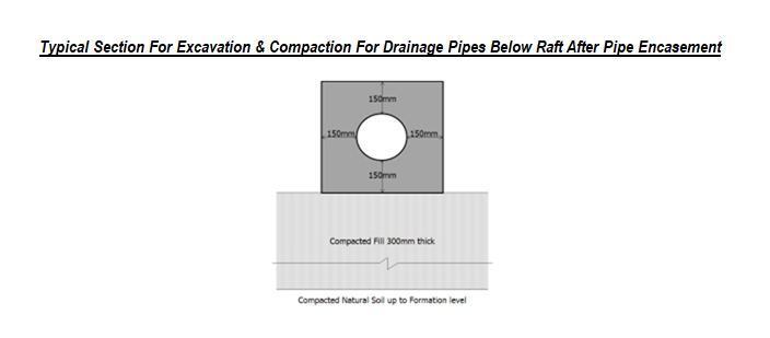
Backfilling
Backfilling above the pipe encasement’s shall be done in 250mm thick layers watered down and compacted to 95%.
Manhole Installation
Excavation
The location of the manholes shall be laid out by the surveyor.
During excavation the depth shall be monitored to prevent over excavation.
Compaction and Testing
The soil at the formation level shall be compacted and tested.
Road Base Filling The excavation shall be back filled to the required level in a 300mm thick road base layer up to the PCC level in accordance to the approved shop drawings and compacted to 95% compaction.

Anti-Termite Treatment
The compacted area ready to receive concrete shall be treated with termicide as per the approved anti termite method statement of the applicator.
Once treatment is complete the area shall be covered by polythene sheet in accordance with the manufacturer’s recommendations.
During backfilling the termicide shall be sprayed after every 1 meter of backfilling.
Casting of PCC
Level tabs or level steel pegs shall fixed by the surveyor. Concrete shall be cast to the pegged level.
During the final finish concrete the levels shall be checked a final time. Once the concrete has set curing shall be started and shall be maintained for 3 days.
Waterproofing & Protection Screed
Before starting the waterproofing works the PCC surface shall be brushed clean of dust and sand.
Waterproofing membrane shall be installed and protected by a 50mm thick screed. The overlap sections shall be protected against damage.
Precast Manhole
The precast manhole shall be cast on site. The steel cage for the manhole shall be constructed and placed in the formwork and the base shall be cast.
Block outs shall be placed and their locations and invert levels shall be confirmed by the surveyor.
Concrete shall be cast using vibrators to ensure compaction.
Curing shall be done for 7days.
Placement of Precast Manholes
The surveyor shall mark out the precast element edges on the blinding surface.
Precast manhole shall be lifted into place.
Dowel bars for the connection to the raft shall be capped to protect from causing injury to the workers.
The internal sides shall be painted with epoxy paint.
Pipe connection
The pipes shall be connected to the manholes and the block outs grouted.
Waterproofing of Sides and Backfilling
The laps from under the blinding shall be cleaned and used to waterproof the sides of the basin.
Protection board shall be fixed. Backfilling shall be done in 200mm thick layers compacted as per specified requirements.
Care shall be taken to prevent damage to the waterproofed sides.
Raft Construction Stages
The following elements shall be cast during the cast of the raft concrete:
Lift Pit Walls
Raft – Manhole connection
Pile Caps
Stage-1: Excavation to Pre concrete pouring
Excavation
The excavation work shall be started taking level readings to ensure that the level excavated does not exceed the required excavation depth.
The exposed formation level shall be well compacted and its density tested.
300mm Sub base Filling
The excavation shall be back filled to the required level in a 300mm thick layer up to the PCC level in accordance to the approved shop drawings and compacted to 95% compaction.
Anti-Termite Treatment
The compacted area ready to receive concrete shall be treated with termicide as per the approved method statement for anti termite from the applicator.
Once treatment is complete the area shall be covered by polythene sheet in accordance with the manufacturer’s recommendations.
Casting of PCC
Level tabs or level steel pegs shall fixed by the surveyor. Concrete shall be cast to the pegged level.
During the final finish concrete the levels shall be checked a final time.
Once the concrete has set curing shall be started and shall be maintained for 7 days.
Waterproofing & Protection screed
Along the perimeter of the raft angle fillets shall be made using sand cement mortar.
The waterproofing system shall be applied in accordance with the manufacturer’s recommendations and the applicator’s approved method statement.
A 50mm thick protection screed shall be cast to ensure that the waterproofing system does not get damaged by the reinforcement bars.
Steel reinforcement
The steel reinforcement shall be fixed for the pile caps, lift pit walls and the raft in accordance with the latest approved shop drawings.
Floor drains and pipes shall be fixed and tested.
All starters bar lengths and locations shall be confirmed by the surveyor.
Side Shutter & Water bar
Plywood shutter shall be built at the perimeter of the raft cast area.
The starter bars of the adjacent raft shall penetrate the shutter.
Care shall be taken to ensure sufficient lap length for the reinforcement is provided.
Water bars shall be fixed secured to ensure there is no movement during casting.
Casting Concrete Preparation
The joint between the old and the fresh concrete shall be chipped and to remove any loose concrete pieces.
Concrete of approved mix shall be ordered after getting approval from the Engineer, before the concreting.
The formwork, steel and the protection screed shall be moistened before placing the concrete.
In any area and at time the concrete protection screed dries out before the concrete of the raft has reached it, it shall be re-sprayed.
A working platform shall be erected around the raft top for a safe and efficient concrete works and shall be inspected by the Site Safety Engineer.
Safe access shall be provided to the top of raft from the existing ground level.
Stage-2: Concrete Pouring Method
- The Site Engineer shall ensure that the concrete area is clean and that all the concreting equipment’s, accessories, manpower, and curing materials with standby are available before the concrete arrives on the site.
- The entire raft shall be illuminated sufficiently ensuring no dark zones are present during concreting.
- After the inspection and approval of the contractor’s QA/QC Engineer, the works shall be offered for the Consultant’s inspection and once approved by consultant structural concrete of approved mix shall be ordered.
- If applicable clearance from municipality for concrete pour shall be taken in advance.
- During placement care shall be taken, not to lose any ingredients from the concrete, any type of segregation, and the displacement of the reinforcement.
- Concrete shall be deposited in uniform layers from the bottom to the required level and shall be consolidated thoroughly using vibrators and pokers but shall not continue so as to cause segregation. The maximum depth of each layer shall be restricted to 300 mm.
- The concrete free fall should be restricted to Max. 2 Meter. For the initial 6 layer shall be poured with the pump’s flexible hose lowered below to the bottom of the raft through the openings at a distance of every 2 Mtr, as shown in the drawing on the top rebar. To facilitate this some of the top rebars shall be removed temporarily after the inspections and tied back after the initial layer concreted.
- Care shall be taken to insert and withdraw vibrators vertically and vibrators are lowered through the full lift of concrete into the lift below, so as to ensure blending of the concrete in the two lift.
- The pouring sequence shall be as shown in the sketches / drawings. The whole raft is divided in to 5 sectors A, B, C, and D & E. And each sector shall be poured from centre towards edge.
- Construction Manager shall be the in-charge of the pour (Pour Master) throughout. He shall control all the activities during the pour (Start and closeouts sequences, supply, vibrations, pour sequence (including extent of each layer & maximum elapsed time before the next layer is placed Etc.)
- There shall be separate pouring gangs (14 No’s) for each pump/sector having 3 No. vibrators each with 3” needle and 2” needle shall be available to vibrate near formworks where ever necessary. There shall be 2 No. vibrators on stand-by making a total of 18 No. vibrators available on site. The entire vibrator shall be equipped with skid pan/ refueling drip tray. There shall be 15 No’s vibrating needle (2” & 3”) also available as stand by.
- At least 4 hours before the commencement of the pour, a training session shall be carried out to instruct all Engineers, Foremen and Vibrator Operators on the specific requirements for vibrating the raft concrete, pouring sequence etc.
- Concreting shall be poured continuously in a sequence to ensure no cold joints occur in the raft. The Engineers and Foreman shall make sure that no layer is left more than 20 minutes without pouring the next layer over it.
- The layer heights and the sequence of locations of the concrete pouring shall be marked on the shutter/steel and shall be well explained to the gang leader.
- Top of the concrete shall be finished “PF” (Power floated) as per the finishing schedule by means of good masons except in the joints.
- The concrete shall be finished from the centre of the raft as per the pour sequence and sufficient perimeter walk way shall be provided wherever necessary.
Curing of Concrete
Concrete shall be cured by water curing methods to minimize shrinkage cracking taking place. As soon as the initial set has taken place and the concrete is able to carry the weight of a man without his weight penetrating the to prevent moisture loss from evaporation and crosswinds, the wet hessian shall be covered with polythene.
100 mm thick polystyrene shall also be placed on top of the raft for the insulation of the concreted structure. The polystyrene shall also be placed on the sides of the raft along the formworks and shall be encapsulated with plastic to prevent moisture loss.
All curing and the insulation shall be maintained for 7 days or until the concrete temperature has stabilized to the Engineer’s satisfaction.
Discover more from Project Management 123
Subscribe to get the latest posts sent to your email.