Dewatering is defined as the removal of the ground water to a level below the normal water table, to enable excavation and construction to be carried out in suitable and safe working condition.
It is proposed to install a single-stage well point system and sump pumps to control the ground water within each excavation area.
WellPoint dewatering involves the installation of riser pipes with a filter section on the lower 1 meter portion, connected into a common header pipe from which the water can be pumped by a vacuum assisted pump to a convenient discharge point
uPVC riser pipes shall be driven into the ground through the use of high pressure water.
A jetting pump is connected to a lance through which the high pressure water is injected into the ground, forming a borehole into which the well point can be installed.
The lance is rotated to create a gap around the well point, which in turn is filled with suitable filter material.
Dewatering works for the proposed development involves the excavation in location as per the following.
- Area to be dewatered : 15.0m X 10.0m
- Maximum excavation level : -5.50m NADD
- Existing Ground level : +0.15m NADD
- Ground water Level : -0.51m NADD
- Shoring : Sheet pile
Well point System
- Aggregate 3/16” crushed and pre-washed aggregate.
- Well points 2” diameter uPVC well points.
- Header Pipes 6” Galvanised steel header pipe.
Sump pump system
- Sump pumps
- Booster Pump (provisional)
- Discharge system complete with necessary valves.
- 3/4” Filter Aggregate
- All necessary equipment
EQUIPMENT
- Auger Drilling Machine (Self-propelled) – if necessary
- High pressure Jetting Pump (12 to 15 bars)
- 6” Dewatering pump (working pump available on site)
- Jetting lance, complete with tank and accessories.
WELLPOINT SYSTEM INSTALLATION
PREPARATION OF HOLDING BRACKETS FOR STEEL HEADER PIPE
Holding brackets must be used to install steel header pipe from 0.5m above the existing water table.
PREDRILLING (if required)
As a mean of ensuring the integrity of the well point installation, boreholes shall be pre-drilled to the required depth at 1m intervals. Pre-drilling shall be executed by the use of a self-propelled drilling rig.
WELLPOINT INSTALLATION
Well points shall be installed into the boreholes at 1m intervals.
High pressure water shall be injected into the ground through the use of a jetting lance; forming a borehole into which the well point shall be inserted.
Once the well point is installed the lance is held in this position until the water being ejected out through the top of the borehole runs clean.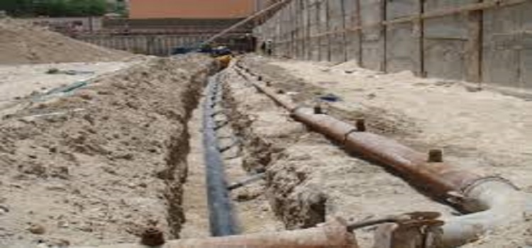
The borehole and well point surrounds are backfilled with aggregate, 10 + 15cm above the working platform.
As the jetting lance is withdrawn from within the borehole, the aggregate shall reduce to 0.0 levels by the displacement created by the removal of the lance.
This procedure is repeated upon installation of each well-point.
HEADER PIPE NETWORK
Upon completion of the installation of the pre-determined number of well-points, the well-points shall be connected to the 6’’ header pipe network by means of swing pipes, which in turn is connected to the dewatering pump.
SUMP PUMP SYSTEM
A sump might be defined as, a pit in which water collects before being bailed or pumped out.
The suction pump will be dipped into a sump to remove the collected water.
By definition, a sump is at a low level in relation to surrounding ground surfaces so that any water will flow to it due to gravity.
For construction projects water is removed from sumps using suction.
Sump pumping is the most basic of the dewatering methods.
In essence, it involves allowing groundwater to seep into the excavation, collecting it in sumps and then pumping it away for disposal.
Sumps are provided for two separate purposes, though the form of a sump may be similar for either requirement i.e.
- To collect surface water run-off channeled to it by means of collector ditches or channels for discharge to a disposal point or area.
- To collect and discharge pumped water due to lowering of the groundwater for a shallow excavation; also sump pumping may be required for gravity drainage to toe drains of battered slopes.
The preferred method of disposal of water collected by the sumps is by means of pumping.
Sump pumps will be strategically located along the excavation to achieve optimum system performance.
FRENCH DRAIN SYSTEM
French Drains involve the installation of gravity drains which channel water to a discharge sump point located at intervals along the drain.
Drains shall be excavated (as required) around the perimeter of the excavation site within the rock layers, using excavators/rock breakers where necessary.
Once excavated the drains shall be filled with a filter aggregate.
The dimension of the drain have been designed as 0.50m wide x 0.50m deep, ensuring a low water velocity in order to provide protection against erosion, whilst at the same time allowing for additional capacity.
French drain network to have a fall of 1%; the actual dimensions and slope of the drain will be calculated as per site conditions.
Intermediate cross drains shall be installed to collect any localized seepage water.
This drain network shall feed to points around the perimeter where the sumps are located within the site, allowing removal of surface water from the site.
DISCHARGE
The collected water produced by the ground water control system shall be discharged into a discharge header main which feeds the water to a settlement tank arrangement prior to discharging to an approved discharge location, in line with the specifications and municipality regulations
Dewatering System Commissioning
Once complete, the dewatering system shall be started with the approval of the main contractor’s representative.
After the first 12 hours of running, all well-point locations shall be observed and adjusted, so that the correct vacuum is created to achieve full efficiency of the dewatering system.
HSE Requirements
Work will be carried out in accordance with project HSE plan and all the relevant safety documentation.
OIL & DIESEL SPILLAGE
Diesels and oils shall be restricted within drip trays to prevent contamination of the sand.
WASTE OIL
Oil disposal units to be situated on site. Waste oil to be removed as and when required by an approved contractor.
SOUND POLLUTION
All diesel generators (if applicable) shall be silent pack units.
PROGRAMME
The dewatering installation shall be dependent on the site access and working space availability.
Dewatering system needs to be installed and operational before the excavation below the water table begins.
After the method statement has been approved, the instruction from the main contractor to begin site mobilization should be given.
Works will be carried out in accordance with the approved program, not taking into account any delays due to authority approvals for the structural works.
Discover more from Project Management 123
Subscribe to get the latest posts sent to your email.