The purpose of this method statement is to make sure that hydrostatic pressure testing of spherical tanks is done safely as per client requirements, specifications and applicable local and international standards.
Method statement is applicable for saturated and unsaturated LPG storage and intermediate tanks.
Project manager has the overall responsibility for implementing and ensuring compliance with this method statement.
References and Regulations
The following reference documents have been utilized in preparing this method statement and shall be referred to additional technical information as necessary.
- ASME Sec. VIII, Div.2 – Ed. 2013
- ASME QCM
- PED 97/23 EC
- ASME Sec. IX – Ed. 2013
- Unfired Pressure Vessel General Project Design Specification
- STGPS – A14
- STGPS C/D1
- Emergency Response Plan
- Waste Management Plan
- Spill Contingency Plan
- Site Quality Control Plan for Sphere Erection
- Weld Book including WPS & PQR
- Welder Performance Qualification Test
- Procedure for Qualification of MT, PT, and VT Personnel
- Magnetic Particle Test (MT) Procedure
- Visual Examination Procedure
- Repair Welding Control Procedure
- Hydro test Procedure
- HSE Plan
- Construction Environmental Control Plan
- Traffic Management Plan
- Emergency Response Plan
- Lifting Plan
- Water Management Plan
- Wind Protection Plan
Necessary Tools & Equipment’s
PWHT Application System (Test fluid-water, pump, calibrated pressure gauges)
CS pipes of Main Header, flanges, plugs, gaskets
Valves and pipes for connection with gauges and the pump, safety valves
Time recorder, Laser-thermometer
Scaffolding Materials
Lifting Equipment & Lifting Plan
Manlifts
Mobile Cranes (Telescopic)
Safety Personnel Protection Materials, safety tapes, warning signs etc.
Welding Machines
Electrode Dryer Oven
Consumables
Grinding/Drilling Machines
Hand Tools
Spherical Tanks Hydrostatic Test General Requirements
Hydrostatic Test that are to be performed by the manufacturers/suppliers shall be specified in the procurement specifications by the Project Manager.
Hydrostatic Test should be performed after completion of all welding and hot works on the pressure parts.
Safety rules and regulations in Hydrostatic Test shall be strictly obeyed during operations.
Safety distance will be at least 15m away from the sphere heated surface during Hydrostatic Test operation.
This area will be isolated by using the safety warning tape.
In order to prevent any accidental damage by vehicles during Hydrostatic Test, suitable warnings such as safety tapes through the test fluid pipes will be provided at site.
Site Supervisor shall prepare the Hydrostatic Test Instructions and Procurement Requisition Specifications in accordance with the project & code specification.
These instructions and specifications shall be reviewed and signed by the Site Manager for their completeness and usage.
Hydrostatic Test shall not be performed in rainy/wet weather conditions.
The Hydrostatic Test will be carried out as specified in ASME SEC.VIII DIV2 Part 8.2 as min-max. test pressures rates, test fluid and metal temperatures.
Hydrostatic Test operations shall be done by subcontractor in accordance with approved procedures and using calibrated instruments and equipment’s.
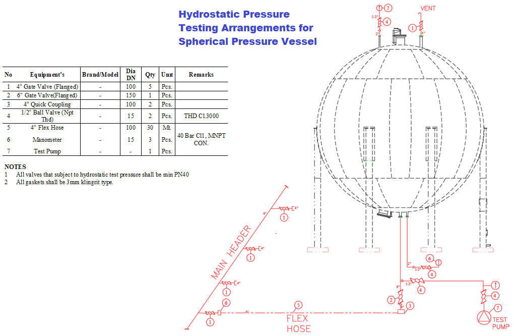
Schedule 40 Carbon Steel pipes will be used in order to bring test fluid to the tanks / area.
Pipe connection will be welded by the qualified welders according to codes & specifications at site.
Internal visual inspections will be done for pipe joints at site.
Pipe to tank connections will be done by flanges and suitable gaskets, rest of opennings on the tank will be closed by blind flanges or plugs except 4’’ level transmittal nozzle(CN1) due to provide air venting.
PREPARATION OF HYDROSTATIC TEST
Prior to hydrostatic testing, it shall be confirmed that all specified nondestructive examinations of welds and inspection have been completed with applicable codes and standards.
It shall be inspected that clips’ and supports’ internal and external welding is completed as per latest approved drawing prior to commencement of hydrostatic test.
During Hydrotest, accessibility for all the joints will be provided for inspector.
Prior to hydrostatic tests; PWHT process shall be already completed for related tanks.
Interior of the tank shall be cleaned.
Prior to test, QC Inspector shall check the equipment and device which will be used as follows:
- The capacity of hydrostatic pump and range of pressure gauges,
- Calibration label attached to the pressure test gauges to assure that the pressure test gauges have been calibrated at least once in every six (6) months and within the calibration due date or if any time there is reason to believe that they are in error.
- The dial indication pressure gage(s) to be used in testing, they should preferably have the dial(s) graduated over a range of about double the intended maximum pressure. But the range shall not be less than 1.5 nor more than 4 (four) times the test pressure.
- The valves and pipe for connection with gauges and the pump.
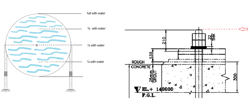
Before the tank is filled with test water, the points for settlement measurement shall be marked on a tank column and the level at measurement points shall be recorded.
Two pressure gauge shall be installed at the top of the tank and two pressure gauge shall be installed at the bottom of tank.
Hydrostatic test continuous recording time and pressure graph shall be provided throughout the testing cycle.
Before test water is filled to the tank, all openings (manholes, nozzles, and fittings) shall be closed and sealed very well by blind flanges and plugs. Only one or two openings at the top of the tank shall be kept open for air venting until the tank is filled completely with water.
For the safety, the tank shall be bound with ropes and warning sign during the test.
Hydrostatic tests shall be carried out using the type of gaskets which be used in service.
Test fluid-water with a chloride content of greater than 250 ppm shall not be used for hydrostatic test as specified.
Metal temperature during a hydrostatic test shall be maintained at least 17°C (30°F) above the minimum design metal temperature of the vessel, but need not exceed 50°C (120°F), to minimize the risk of brittle fracture.
APPLICATION OF PRESSURE FOR HYDRO TESTING
FILLING WATER
Top level transmittal nozzle will be left open at the high point of the tank, where it will be possible to purge the air while the tank is being filled.
Fill sphere ¼ with water, wait at least 2 hours; Check column base elevation.
Fill sphere ½ with water, wait at least 6 hours; Check column base elevation.
Turn buckles of sway rods shall be tightening by torqueing at least 7406 N.m as per project during that period.
Fill sphere¾ with water;Wait at least 2 hours; Check column base elevation.
Fill sphere full with water;Wait at least 2 hours; Check column base elevation.
Check of each columns base elevation will be taken from the top of the anchor as seen below at each stage by the survey.
Pressure Application
The test pressure shall not be applied until the vessel and the test fluid are at about the same temperature.
Temperature records will be taken by calibrated laser-thermometer frequently.
Hydrostatic pressure shall be gradually increased until the test pressure is reached.
When the test pressure is reached, the valve on the pump is to be shut off.
The hydrostatic test pressure of a completed vessel shall not exceed the values which are mentioned in factory test reports.
Pressure shall then be reduced to a value not less than the test pressure divided by 1.43 before examining for leakage.
Hydrostatic test pressure shall be held for a minimum of one hour per 25mm of shell thickness and in no case less than one hour.
Following the reduction of the test pressure to the level indicated, a visual examination for leakage shall be made by the inspector of all joints and connections and of all regions of high stress such as knuckle of formed heads, cone to cylinder junctions, regions around openings and thickness transitions.
Any leaks that are present, except for that leakage that may occur at temporary test closures for those openings intended for welded connections, shall be corrected and the vessel shall be retested.
Repairs will be carried on according to Assigned WPSs. After repair, shall be retested by Magnetic or Liquid Penetrant Test according to related Codes & Specs.
After completion of the hydrostatic test, vents and drains shall be opened to remove all water from the tank, and the emptying rate shall be so adjusted to avoid any vacuum.
There will be a safety valve on the bottom nozzle of the tank in order to interfere in any case of overpressure during hydrostatic pressure test.
Hydrostatic test shall be carried out in presence of Owner/PMC, Contractor and consultant.
After complete draining of the test water, final readings of the foundation settlements shall be made.
Each readings of the support columns on the planar tilt of foundation by the time of before & during, filling water and after draining of the test water shall not be greater than 15mm.
Quality Control & Inspections
QC inspector shall be responsible for inspection of all attributes defined in this section.
Joints have been properly prepared in accordance with this method statement.
QC Inspector shall also review the information of the Hydrostatic test graphs, holding times and settlement readings.
If the all information is correct, he shall sign and date the Hydrostatic Test Report.
Reinforcing pads of manhole & nozzles shall be pneumatically (bubble leakage test) tested at a minimum pressure of 0.6 kg/cm² prior to hydrostatic test. (No need to perform bubble leakage test again, if the manufacturer has already performed it before at shop). After hydrostatic test completion, spin holes of R.F. Pads will be closed with grease oil.
Upon completion of the Hydrostatic Test operation, QC Inspector shall verify that all temporary attachments have been removed.
In process monitoring of all Hydrostatic Test operations shall be performed by QC Inspector.
After hydrostatic testing has been satisfactorily completed, the vessel shall be re-checked by inspectors for out-of-roundness and for bow.
After completion of Hydrostatic Test operation, QC Inspector shall submit the all Hydrostatic Test reports and documents for monitoring and approval.
Relevant Records & Certificates
Hydrostatic test equipment’s shall be provided with valid calibration and test certificates.
Base elevation readings shall be recorded for each column of the tank as in before-during-after hydrostatic test operation.
The Hydrostatic Test Operator shall indicate the description of elevation read parts, the job no, date of hydrostatic test, min-max test fluid temperature, water fill rates, holding times, test pressure at the top & bottom of vessel, pressure holding time and test position.
QC personnel shall record the results of hydrostatic test using the Pressure Test Report which shall be reviewed and approved by the Site Manager. This report shall be presented to client/consultant for his review and acceptance.
If the result of the test is acceptable; QC Personnel, Site Manager and the client representative shall sign and date the Pressure Test Report and quality control procedure.
JSA for Hydrostatic test of Spherical tanks (Including night shift)
| No | Description of task | Hazards | Control Measures to be Enforced |
| 1 | Planning |
|
|
| 2 | Hydrostatic test |
|
|
| 3 | Hydrostatic Test Works during night shift activity |
|
|
| 4 | Housekeeping | Slip, Trip, Falls |
|
| 5 | Material Handling (Manual/Mechanical) |
|
|
| 6 | Hot Work (welding/cutting/grinding) |
|
|
| 7 | Working at height |
|
|
| 8 | Emergency situations | Any Injury |
|
Discover more from Project Management 123
Subscribe to get the latest posts sent to your email.