Below is a brief method statement for construction of non disruptive road crossing by using the HDD drilling method.
List of Equipment, Machinery & Materials
Drilling Machine
Jet Assembly (Drilling head , water tanker & Bentonite mix )
Transmitter, Receiver and Wire line
Reamer Tool
Welding Machine
Towing head
Swivel and Polymers Extenders
Roles and Responsibilities
Site/Project Manager: To arrange all the pre-requisites, to arrange for Inspections with prior information to the Client / Consultant, supervising all construction activities.
Project Engineer: To ensure compliance of related procedures, to keep all the related documents and drawings at the work place, supervising all construction activities as per the approved procedures, to carry out the Inspections.
QA/QC Engineer: To ensure all work activities are carried in accordance with the Project Quality Plan and method statements, Control of non-conformity.
HSE Engineer: To Implement the project safety plan aspects, to Issue PPE’s to all the personnel, Inform project site manager about unsafe conditions and ensure those are rectified, to conduct safety meetings, arrange safety signs and display boards, Investigate all the accidents and circulate the learning points, and report to head office..
Drilling In-charge: To ensure all activities to be carried out as per approved procedures in the required time limit.
Civil Foreman: To carry out all the civil related works.
Pre Requisites for Construction of Non Disruptive Road Crossing
Permits, licenses or approval letters issued by government or statutory bodies have been issued and are available at site.
Approved drawings are available on site
Mark the location of the road crossing, entry and exit pit as per the drawing.
Excavate the entry and exit pit of 4 mts length, 4 mtr wide and depth should be as per drawing depending upon the existing services.
Locate all the existing services in the work area by trial pits. The foot path and centre median of the road can also be exposed, if required.
If excavation is more than 1.5 m deep, step excavation should be done or shoring shall be provided.
If the drilling tool comes across a boulder during drilling operation, break it by using Hard Rock breaking tool and if not possible then divert the route to avoid such obstructions, upon approval from the consulting engineers.
The contractor shall monitor road levels before and after drilling work, monthly for a period of six months. The result of levels is to be informed to authorities concerned. If settlement occurred due to drilling under asphalted road is found to be more than the Calculated Value, contractor shall report the findings immediately to client.
Ensure all the safety measures have been taken.
Specific HSE Control Measures for the Work Location
While drilling, reaming and pulling preventive measures are made to minimize down Hole pressures or erosions.
The drilling fluid flow is analyzed to adjust hole dimensions, geological properties, flow rates, viscosity, gel strength, filtrate and solids content to the annular flow. Geological properties in the annulus are measured in the field and adjusted as required to conform to the analyzed circuit and ground conditions.
Issue personal protective equipment to all site personnel appropriate to their nature of works. Comply with safety local standards.
Comply with local police guidelines in the Temporary Signing requirements.
Safety precautions to be maintained for the personnel, Pedestrians and environment within the occupied area, all as per approved HSE manual.
Attention shall be paid to regular site cleaning and keeping the working area as confined as possible.
Method for Construction of Non Disruptive Road Crossing
The guided pilot hole:
To drill soft sediments like clay, sand and medium gravel the rotating drilling head has to cut a micro tunnel into the soil supported by a high-pressure jet of water and bentonite mix.
This equipment is called a jet assembly. The drilled soiled material flows back into the start pit, transported by the drilling mud.
The size of the pilot hole is approx.70 mm and the mudflow is approx.40 ltr/min and the pressure is about 60 bars.
To follow the designed drill run, the drilling tool is equipped with a transmitter, which is given permanent information about the depth, the distance, the inclination and the direction of the drilling tool. This information is reported on a drilling report to provide the as-built documents.
The transmitter gives a signal to the surface above, which is received by a receiver and recorded as down hole data, for future reference.
To follow the drilling tool one person will walk and stay over the tool and hold the receiver. On road crossings one lane has to be blocked for few minutes while the drilling tool is moving under it. While closing the road, traffic-engineering rule has to be followed.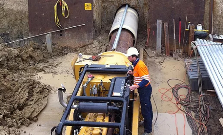
The receiver sends the information to a remote control panel on the drilling rig. The driller can correct the position of the drilling tool and can keep it in the desired level & direction.
All the information of the depth, distance and inclination are sent from down hole through a wire line in the drill rod into the computer. The steering engineer and the driller can keep the drilling tool on the designed curve.
During drilling the position of pilot hole is recorded every 3 meter along its route and this data will form a part of the as-built records of the HDD crossing.
Reaming of Pilot Hole
When the pilot hole reaches the exit pit the drill equipment will be re-placed and connected to the pullback assembly called a reamer tool.
There are different shapes of reamers that enable you to cut soft and hard formations.
The number of reaming steps depends on the diameter of the pipe and the hardness of the geological formations.
These operations always start with a small-scale reamer and end with a diameter that is around 1.2 times bigger than the overall bundle diameter.
Behind the reamer, drill rods are pulled into the hole, so as to keep a to and fro motion on the drilling operation, also to maintain an opportunity to with draw & re-position the reaming tool should the geological structure change.
Installation of the product pipe
While reaming the bore hole the pipe is Fusion or Butt welded (Fusion or Butt welding method on PE-HD pipes) to the full length of the drill run and is formed into a tied bundle of individual pipes. It is placed in line of the drill run behind the exit pit.
After the last reaming step is finished, the pipe is connected to the reamer with a towing head and the swivel.
The swivel is used to prevent the pipe bundle from rotating, because the reamer will rotate continuously during the operation of pulling back the pipe bundle so as to ensure a clean bore hole is maintained during this pulling in of the bundle operation.
Drilling Mud
The directional crossing process requires the use of Bentonite slurry that provides the following functions:
- Hydraulic cutting jet.
- Lubrication to the drilling tool and drilling rods.
- Transport drill-cut material (sand etc.) to the start or exit pit.
- Stabilize the hole against collapse while drilling and reaming.
- Make a filter-cake to guard against loss of slurry into surrounding formations.
Slurry Composition
The slurries most commonly used are bentonite based. Often polymers extenders are also added to enhance certain characteristics.
Pump Volume and Pressure
For each project, a drilling fluid calculation is made according to the ground conditions, the hole size, hole length, pump volume and pump pressure.
To drill a pilot hole in sand with a 12-ton machine, a pump volume from 40-50 liter/min and a pressure from 30-40 bar is required. The jets are facing forward and they are making tunnel with approximately 20-80 mm diameter.
To ream the hole to 360 mm diameter a pump volume from 50-70 liter/min. and a pressure from 20-30 bar is used. To pull the pipe, a volume from 40-60 liter/min. and a pressure from 20-30 bar is used.
A mandrill test will be performed on the installed pipes after completion of grouting procedure hence confirming the suitability of the HDD crossing at its completion.
Discover more from Project Management 123
Subscribe to get the latest posts sent to your email.