This pages mentions requirements for the provision of design, manufacture, supply, delivery, storage, assembly, fixing, installation, testing and commissioning of curtain walling system and all windows and glazed spandrels
The Contractor will be required to produce full working drawings and details showing the construction, fabrication or manufacture, assembly and installation of the curtain wall system. Two copies of all working drawings are to be submitted to the consultant for approval in accordance with the Contractor’s approved Program of Works. One copy of each drawing will be returned to the Contractor with approval or comments as the case may be.
The Contractor shall thereafter at his own expense supply four additional copies of his approved working drawings for the use of the consultant. Working drawings shall be full size in so far as is practical and shall show dimensions, types of materials, finishes, size and location of joints, anchors, fixings, etc., as well as the following:
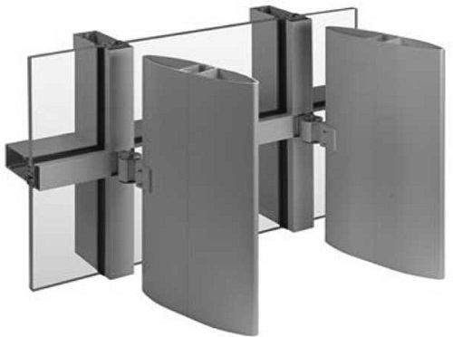
- Head, sill, jamb and corner details, mullions, members, profiles, joint location and sizes, arrangement of units, horizontal to vertical connections, baffles, flashings and insulation systems.
- Junctions with and anchorage to the building structure
- Glazing details and methods of installation including location of various types and thicknesses of glass
- Air barriers and vapour barriers
- Dielectric separator details
- Thermal separator details
- Provision for thermally induced expansion and contraction of members
- Provision for accommodation of movements of the building structure
- Water drainage system
- Details at parapets
- Pressure equalisation system
Laboratory testing Requirements
The Contractor shall be responsible for testing of the curtain walling system at an approved laboratory. All testing shall be witnessed by the consultant. The Contractor shall ensure that all labour, materials, products, including test prototypes, equipment, facilities, laboratory test chambers and monitoring equipment and other services are available to perform testing work. Testing shall be carried out in accordance with AAMA 501-83 and the ASTM standards referred to therein and shall comprise the following:
Static Test – Structural
Required results:
- The inward deflection of any part of the test piece shall not be sufficient to cause any member to touch any part of the main structure or impose loads onto any non-load bearing interior wall members.
- All components shall return to their original position under zero load, demonstrating that the elastic limits of the materials have not been exceeded.
- Anchorages shall not show permanent set or signs of slackening off.
- No noise shall occur due to movement of components
- Deflections shall not exceed the tolerances set out in this Specification.
Static Test – Water Penetration
Required results:
- No infiltration of water through the cladding.
Static Test – Air Infiltration / Exfiltration
Required result:
- Not exceeding the limits set out in this Specification and no draughts.
Testing shall be carried out in the following sequence:
- Static, negative and negative for air infiltration/exfiltration
- Static, positive at 20% of maximum design load for water penetration
- Static, positive and negative at 50% maximum design load for structural and deflection performance
- Static, positive and negative at 100% maximum design load for structural and deflection performance
- Repeat static, negative at 20% maximum design load for water penetration
On completion of testing the Contractor shall submit to the consultant four copies of signed certified test reports. Drawings of each test specimen showing overall dimensions, details of construction, types of materials, sizes and locations of components, types and location of seals, connection to the test frame, location of pressure and deflection gauges and similar data.
Number of repeat tests made and modifications made to each specimen
Photographs of the test processes, labelled by subject, date and project.
List of tests, test results and comparison with specified requirements
Description of effect of tests on finishes and/or any other defects or failures disclosed by the tests.
Material Storage and Handling
All materials which will be exposed to atmospheric heat and which will be exposed to sunlight, including exposure through glass, shall be formulated so as not to lose their properties, including colour fastness, due to exposure to heat and due to exposure to ultra violet radiation. Materials and finishes shall be selected and supplied as follows:
- Aluminium extrusions shall be 6063 alloy, T5 temper, or Al mgsi 5 F 22 anodising quality or equal to the approval of the Engineer
- Aluminium sheet and plates shall be 1100-H14 alloy, anodising quality or equal to the approval of the company.
- Exposed aluminium shall be provided with a white factory-applied three coat Duranar XL (PVF2) finish, comprising a primer, a coloured top coat and a clear protective coat to a total finished thickness of not less than 40 microns. The coating shall be provided by a manufacturer approved by the consultant.
- Steel shall comply with the requirements of BS 5950 and with Section 5 of this Specification. Steel in the interior of the building or otherwise not exposed to the exterior environment shall be primed with an approved rust inhibiting primer. Steel at the building exterior or in exterior assemblies shall be galvanised unless shown otherwise on the Drawings.
- Screws, bolts, washers, nuts and other fastening devices shall be austenitic grade stainless steel. Exposed fastenings shall be finished to match the finish and colour of the material in which they occur.
- Slip washers shall be of nylon
- Thermal separators shall be Polythermid insulators or equal to the approval of the consultant.
- Dielectric separators shall be of bituminous paint to BS 6949, tape or dielectric coating to the approval of the consultant.
- Insulation in frames and between frames and adjacent construction shall comprise lightweight inorganic mineral wool of 50 kg per cu. m nominal density.
- Firestopping shall comprise mineral fibre insulation with galvanised mild steel and shall be 25% wider than the space to be filled. Firestopping sealant shall comprise silicone or silicone based materials as manufactured by Tremco, Dow Corning Ltd., General Electric Ltd., or Rhone-Poulenc Inc., or equal to the approval of the company.
- Non-structural sealants shall be medium modulus silicone sealants as manufactured by General Electric Ltd., Dow Corning Ltd., or similar to the approval of the company.
- Structural sealants shall comprise silicone sealants in accordance with ASTM C 920 black colour, General Electric Ultraglaze SSG 4200 or Dow Corning 983, all to the approval of the company.
- All sealants shall be applied strictly in accordance with the manufacturer’s recommendations.
- Glass shall comply with the requirements of Section 8B of this Specification. Glass and glazing units shall be distortion free and shall be fixed in place using glazing compound, spacers, setting blocks, shims, glazing tapes and gaskets, all to the approval of the company.
The Contractor shall submit material samples as follows for approval:
- Extrusions 300 mm long
- Sheets 300 mm x 300 mm
- Gaskets and tapes 900 mm long section of each type
- Sealants 150 mm bead strips applied to sheet metal
- Fasteners 3 of each type
- Glass 300 mm x 300 mm of each type
- All materials used in the finished work shall conform in terms of quality, physical and mechanical characteristics and finish with the approved samples.
Doors in curtain walling
The Contractor shall supply and install, and allow in the design and manufacture of the curtain walling for, balcony access doors in the locations shown on the Drawings, comprising a double glazed leaf with anodised aluminium framing (the double glazing unit and the aluminium framing to be as described in Division 8. All doors shall be fitted with secondary insect screen door. All doors shall have ironmongery including locks as specified in the Schedule of Doors.
Curtain Walling Design
The Contractor shall be fully responsible for the final design of the curtain walling and shall supply calculations, test certificates and performance guarantees in accordance with the requirements of this Section of the Specification. Any structural design data shown on the drawings is for tender purposes only and not to be taken as actual nor shall it relieve the Contractor from any responsibility for the design of the curtain walling system. The curtain wall system shall comply with the following design requirements and shall be designed with the design data hereunder:
The framework shall be capable of carrying it’s own weight and all loads applied to it (including loads from the window cleaning equipment) without damage, distortion or deflection in excess of the limits defined below.
Allowable tolerances after installation shall be as follows:
Vertical plus/minus 2mm
Horizontal plus/minus 2 mm
Racking in elevation nil
Deviation in plumb over full height 6 mm
Deviation in plane over full width of each building face 6 mm
(Tolerances are not accumulative)
- Vertical members shall not suffer deflection under any load or combination of loads in excess of 1/240 of the span or 10mm whichever is the less.
- Horizontal members shall not suffer deflection under any load or combination of loads in excess of more 1/240 of the span or one half of the allowable clearance for the glass whichever is the less.
- Infill panels shall be so fixed that they will not suffer distortion, damage or displacement under the action of any of the forces to which they may be subjected including those specified hereunder. Panels shall be designed so that they may be individually removed without removing adjacent metal panels or glazed units.
- The curtain wall system shall be designed to accommodate thermal expansion and contraction over a temperature range of 10 deg C to 60 deg C with an internal temperature of 22 deg. C, as well as differential thermal movement where part of an elevation is shaded. The system shall be designed to accommodate expansion and contractions due to cyclic heat gain and loss from the absorption of heat which may cause components of the system to get hotter than the temperatures described herein. The U-value of the system shall not exceed 2.8 W per sq.m K. Thermal breaks shall be provided between interior and exterior components to prevent thermal bridges being formed.
- The system shall be designed to withstand a wind loading due to winds of speeds up to (140 kph). The design shall include for both positive and negative pressures due to wind and shall make all necessary allowance for impact, suction, up-lift and gusting and for the shape of the building, its height and the proximity of adjacent buildings.
- The curtain wall and structural glazing systems shall be weather tight and clip on glazing beads shall not be used in exterior or lightly exposed locations. The system shall allow for pressure equalisation and shall be provided with baffles to prevent air flow within components and to prevent the entry of rainwater and sand. Air movement through the system, from building interior to building exterior and from building exterior to building interior shall not exceed the following when operating under a static pressure difference of 75 Pa:
Fixed elements: 1.08 cu.m/hr/sq.m
Openable elements (when closed) 0.55 cu.m/hr/m
- Condensation or any water which may pass the external weather barrier shall be caught in internal gutters and carried to the outside through a system of weepholes so protected by an exterior shield that blowback through the weepholes will be prevented. A minimum of one weephole of 6mm diameter per 0.5m2 of wall shall be provided.
- The system shall be provided with a continuous fire and smoke seal at the junction between the edges of suspended concrete slabs and the building envelope to prevent the passage of fire and smoke from floor to floor and from floor to roof.
- Openable vision panels shall be fitted with fully retractable roller type – with ratchet operation – gauze insect screen including boxing in at head to integrate with transoms and mullions and side guide rails.
Curtain Wall Fabrication and Erection
Work shall be executed by tradesmen skilled in curtain wall fabrication, assembly and erection. Joints shall be square and true and hairline except where joint design calls for expansion and contraction. Exposed work shall be free of machine marks or dimpling. Components shall be fabricated to avoid the necessity for force fitting. The systems shall be designed, fabricated and erected to accommodate building tolerances.
The Contractor will be responsible for taking field measurements and levels as necessary to verify or supplement those shown on the Drawings and for coordinating dimensional tolerances in adjacent building elements. Anchorages and fixings to the building structure shall be carried out in accordance with the details shown on the approved working drawings.
Welding shall be carried out using inert metal arc welding equipment. Exposed welds shall be continuous and finished flush, without deformation of exposed metal or the system finishes. Welded joints of steel members shall be of adequate strength and durability with joints tight and flush. Where it is necessary to weld components already galvanized remove galvanizing for 50 mm around the area to be welded and make good with primer and protective paint.
Frames shall be reinforced by concealed means as necessary to meet the specified design conditions. Steel brackets and supporting frames shall be provided to hold the frames in place in openings. Slotted connections shall be provided as required to accommodate deflection of components and/or the deflection of the structure. Hairline joints at junctions with frame members shall be sealed by gun injection from the interior to ensure a continuous seal of the joint. Beads in the glazing space shall not be allowed to impair sealing of glazing materials. Excess sealant forced onto the face of frame assemblies shall be carefully cleaned off to the satisfaction of the company.
Where frame members are lapped the faces exposed to the weather shall be in full tight contact with minimal clearance for snap-on components. Plate assemblies shall be fastened in place using concealed clips. Erection of the curtain wall shall not be started until the building structure has been inspected to ensure that all surfaces and openings are correctly prepared ready to receive the installation. Inspection of the structure in stages to receive staged areas of curtain wall installation in accordance with the Contractor’s agreed programme of construction and completion will be allowed at the discretion of the company.
The curtain wall system shall be erected plumb, square, level and in correct relationship to the building structure. All devices for anchoring the frame assemblies to the building structure shall have sufficient adjustment to permit correct and accurate alignment. After alignment anchorages shall be rivetted, welded or positively locked to prevent movement other than that designed for expansion and contraction. Drilling of concrete to accommodate anchorages shall be carried out with care to avoid damage the building structure. All such damage shall be made good to the satisfaction of the company.
Contractor shall include for the supply and installation of all parapet, coping and cap flashings between the curtain wall and the building structure and shall ensure the continuity of thermal and air barriers as well as providing air tight seals at air barrier penetrations for mechanical and electrical services. On completion of the installation and immediately before the building is handed over the Contractor shall clean all metal and glass, inspect all units for damage, replacing damaged units as required, adjust all operating devices, window and doors to full and trouble free operation and hand over the installation in a sound condition to the approval of the company.
Method of erection
The Contractor shall take surveys and measurements as necessary for preparation of designs, drawings or other documentation. Approved working drawings shall constitute the basis for fabrication of materials to be provided and no fabrication shall commence until working drawings have been approved.
Discover more from Project Management 123
Subscribe to get the latest posts sent to your email.