Below is a brief HVAC method statement that covers the Installation air conditioning split unit.
By following this procedure installer will ensure that the installation has been carried out as per contract specifications and manufacturer’s recommendations.
The method statement gives details of how the ac installation work will be carried out and the how the health and safety issues and controls shall be implemented.
Split units will be supplied on pallets unless otherwise specified, and will be offloaded from the delivery vehicle using a forklift or similar equipment. Under no circumstances must the units be handled in such a way as to cause damage to the peripheral connections, other fittings etc.
Should it be necessary to store units on site for longer period of time prior to installation, they must be stored in a clean, dry, secure area, where any possibility of damage to the units is eliminated.
The minimum Personal Protective Equipment (PPE) on site is:
- Hard hat
- Safety boots
- High-visibility vest
- Gloves
- Goggles/Glasses
Below is list of mandatory tools for doing the split / mini split installation works, all tools & instruments shall be of proper quality, safe for use and calibrated.
- Ladder and other lifting equipment
- Spirit Level
- Electric Drill
- Measuring Tape
- Hand Hammer and Punching Tool
- Adjustable Wrench
- Mobile Hoist or other suitable equipment
Split & Packaged Unit Installation Method Statement Package – Download Editable Files
Split Unit Pre Installation Requirements
A pre-start meeting prior to the commencement of the ac split installation works will take place with the Site Engineer, H&S Officer, QC Engineer, Supervisor/Foreman in charge to address the following:
QC engineer shall raise material inspection for consultant inspection and approval, before starting installation works.
The approved shop drawings and approved manufacturer’s technical literature must be available on site prior to start of ac installation work.
All split system AC units and related equipment to be installed as per approved technical submittals.
Check the accessibility of the service and maintenance including return air filter.
Condensate drain can be run continuously downhill from the unit to over board fittings.
Make sure that the unit complies with technical specifications and verify the side connection of copper tube flare connects.
Check the connecting drain pan with drains pipes are running continuously without any clashing with architectural and discharging properly.
Verify the color of the cabinet by the architect.
Verify he flare connection side before refrigerant copper piping and verify the refrigerant liquid as per manufacturer’s recommendations
Installation Of Wall Mounted Indoor Units
Before drilling the holes for the supports, check if there’s any services embedded on the wall such as electrical cables or pipes to prevent damage.
Cross check with the coordination drawings and MEP Site Engineer to avoid clashes in services.
Make sure that indoor unit should be installed horizontally in such a way that the water can easily drain out through the pipe under the gravity.
Do not install indoor unit above any of electrical equipment.
Indoor mini split unit needs at least 6 inches (15 cm) of open space from its top and sides, and it needs to be at least 8 feet (2.5 meters) from the ground, or as per the manufacturer standard and height as per the approved layout.
Hold the mounting plate against the wall where you want to install the indoor unit.
Use a level to make sure the plate is both horizontally and vertically square. Mark the location of holes.
Drill holes at the appropriate spots to affix the plate to the wall. Insert plastic anchors into the holes. Secure the plate to the wall with tapping screws.
Manually lift up the indoor unit with the aid of a ladder or suitable platform/scaffolding.
Secure the indoor unit to the mounting plate by pressing the unit against the mounting plate.
Split & Packaged Unit Installation Method Statement Package – Download Editable Files
Find the best spot for the wall opening / hole, bearing in mind the length of the pipe and that it needs to reach from the indoor unit.
The hole should be no bigger than 3 inches (7.5 cm) in diameter and needs to slope downward toward the exterior / drain.
Insert a approved sleeve into the hole, into which sealant will be applied after pipe is installed.
Run the piping and electrical cables from the indoor unit toward the hole drilled through the wall.
Insulate the copper piping by approved insulation material.
Bind the copper pipes, the power cables and the drain pipe together with electrical tape. Place the drain pipe on the bottom to ensure a free flow of water.
Remove the pipe cap and remove any debris.
Secure the pipe to the indoor unit. Use 2 wrenches, working in opposite directions, to tighten the connection.
Join the water drainage pipe to the indoor unit’s base.
Tilting the indoor unit – the indoor unit is given slight tilt of about 2-3 degrees towards the drain pipe.
This enables unhindered flow condensate drain water towards the water space where drain water is collected and drain pipe is connected for removal of water. This angle should be just sufficient to enable flow of water without disturbing the looks of the indoor unit due to high angle of tilt.
Also connect the control cables as per approved diagrams.
Indoor Unit Installation Ceiling Mounted
Before installing the units in position ensure that sufficient space for carrying out installation as well as routine and extraordinary maintenance work (such as removal of parts), is available.
There will be no obstructions for air intake and delivery.
Select the correct size I model of split AC and bring the unit to the location as configured in the shop drawing.
Check the split unit, installation accessories like anchor, threaded rod, rod connector and tools etc. are placed at the location.
Place the indoor split unit as close as possible to the place of installation. Don’t place tools or any kind of weight on top of the unit.
Erect the proper scaffolding or make a proper work platform at the work location.
Determine the position of the supports as per the location in approved shop and coordination drawings and mark out on the concrete.
Select the appropriate size anchor bolt & drill the holes in the concrete accordingly.
Install the anchor in the concrete structure then fix the threaded rod of correct length to the anchor then provide the approved vibration isolator.
Lift the unit properly with proper resources (men, tools or equipment) and then insert the other end of installed rod in the relative slots and provide check nut as well as lock nuts.
Once the units are installed in situ, prior to commissioning, they must still be protected from damage.
Pipe connection to be done after placing the unit on the supports, as per approved drawings.
All wiring must comply with the technical specifications requirements and the approved shop drawings.
Drain tray connection fittings should not cause condensate to be held back in the tray.
A parallel thread, shouldered fitting of the correct thread length should be used and packing washers added where necessary to ensure correct draining of bottom outlet drain trays.
Outdoor Unit Installation
Base for the outdoor unit to be prepared as per the approved drawings. Bases should be at least 100mm extra all around.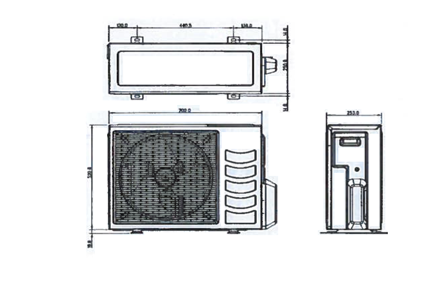
There should be at least 600mm open space at the discharge side of unit or advised by the manufacturer.
Mark the hole as per the base frame of unit. Drill the hole and push the anchor inside the hole.
Now install the unit on base matching the base frame hole with the drilled hole.
Provide approved antivibration pad between the concrete base and base frame of unit.
Insert the threaded rod through the base frame hole of unit and tighten it into the grouted anchor and then provide the check nut and tighten it properly.
Provide proper space all around the unit for future maintenance.
Split & Packaged Unit Installation Method Statement Package – Download Editable Files
Discover more from Project Management 123
Subscribe to get the latest posts sent to your email.