Below you can find a complete Project Specific Construction Methodology.
Following are the sections or table of content included in the document:
1.0 Civil Works
2.0 Block Work
3.0 Plastering
4.0 Ceramic Floor and Wall Tiles – Granite and Terrazzo Tiles
5.0 Painting
6.0 Aluminium
7.0 Suspended Ceilings
8.0 External Works
9.0 Mechanical, Electrical & Plumbing (MEP) Works
10.0 Air Conditioning – Duct Fabrication
11.0 Air Conditioning – Ductwork Installation
12.0 Ductwork Insulation
13.0 Aluminium Cladding of Insulated Duct and Pipes
14.0 Chiller Water Pipe Insulation
15.0 Plumbing
16.0 Electrical Work
1.0 Construction methodology for civil works
1.1 Contractor will commence the project following the Client’s requirements. Upon award of contract, site inspection and site take over will be done. Any differences will be brought to the attention of the Client or Consultant prior commencement of works.
1.2 Site clearance works & excavation for foundations (pile caps) will be done with machines and labor where necessary.
1.3 Pile head treatment will follow excavation and completion of blinding. Pile head protection will be done in accordance to the drawings and specifications
1.4 Raft foundation (Pile Cap) with he constructed by conventional cast insitu concrete. Certain parts of forms will be carried out as solid block work ready for application of waterproofing. Formwork will be prepared on a modular basis and comprise timber facing and timber stiffening horizontal and vertical.
1.5 Horizontal waterproofing will be applied to blinding as specified then protected with the cement sand screed before construction activities for raft stab (fixing of reinforcement, forms for construction joints and pouring of concrete). Vertical waterproofing will be applied onto plastered surface of block wall and protected with bituminous boards.
1.6 Superstructure will be carried our according to the drawings arid specifications. Vertical and horizontal members will be cast insitu concrete elements. Concrete walls will be constructed as an insitu pour cast as a single lift for each level. Form walls of timber suitably braced to ensure proper level and alignment and would ho prepared on a modular basis for reuse on each level. Tie rod supports will be provided to ensure proper alignment and bracing of the shutters.
1.7 Simultaneously with the progress of the concrete structure first fixing of M.E.P works will follow.
1.8 Hoists will carry out vertical transportation of material and labor. Erection of hoists will be in several stages following vertical progress of main structure.
1.9 On completion of concrete works for some of the floors, the block work, plaster and screed work will proceed.
1.10. Tiling (ceramic, e.g.) will then proceed. All completed floor tiling will be protected by means of gypsum plaster or plywood covering which will be re moved and cleared before handover.
1.11 Building finishes will be applied, by completing wet building finishes on one section before starting dry building finishes. Where possible, building finishes will start from top to bottom to avoid damaging previously completed work. Work will also proceed linearly over a particular part of rooms; wet finishes on half of the block will be completed before dry finishes start
1.12 Dry finishes like false ceiling, framing carpentry, aluminum etc. will then proceed together with priming for paint.
1.13 Commencement of aluminum (Curtain wall will start from the bottom to top. Upon completion half of the concrete structure for building, fixing of curtain wall will start.
1.14 Progress of curtain wall and finishes will be followed with the second fixing of M.EP. works.
1.15 Installation of chillier units will be advanced in order to commencement air conditioning of certain portions of the building, which can provide completion of al finishes.
1.16 Installation of lifts will advance as soon as concrete structure is finished.
1.17 Painting will be completed except for the last coat, which will follow the completion of all dry finishing’s and MEP pre-commissioning activities.
1.18 External pavement and kerbstones will commence after completion of external envelope.
Download Full Civil Construction Method Statement Bundle – Covering 42 Activities

2.0 Block Work
Detailed method statement must he prepared specifically identifying material types, quality of finish and other important aspects.
2.1 Block work will commence upon removal of scaffolding and formwork. Block work on the ground will commence after completion of slab for 2nd floor.
2.2 Concrete blocks supplied for site will be certified by Consultant. Mortar will be mixed on site according to the specifications and trail mixes approved by Consultant. Standard accessories with approvals by Consultant will be used.
2.3 Alignment and level of the adjacent concrete works must be checked prior to placing blockwork.
2.4 Adequate arrangements of urn for curing of block work will be provided according to the specifications.
2.5 All junction details with reinforced concrete frame will be carried out according to the previous approved drawings.
2.6 Upon completion of block work, chasing of walls will commence to provide all necessary’ conducting. Preparation for plastering, fixing of angle beads and other accessories and applying of rush coat will follow.
3.0 Plastering
3.1 Before commencement of plaster work it will be ensured that block work has been laid to the true line and level.
3.2 All cut outs or voids in the block work will be filled or treated. Block work will be properly filled with mortar and pointed. Required building services will he installed prior to commencement of plaster work.
3.3 Trial panel area of work will completed and approved before commencement of plastering on all areas.
4.0 Ceramic Floor and Wall Tiles – Granite and Terrazzo Tiles
4.1 Detailed tiling method statement will be prepared specifically identifying material types, quality of finish and other important aspects upon award of the contract.
4.2 Ceramic tiles and fixing method will be as approved by Consultant prior to procurement of same and delivery to site.
4.3 Before commencement of tiling works in wet areas waterproofing of the floor will be tested and approved by Consultant.
4.4 Pattern of laying tiles will be identified and clearly marked. Also, setting out of the tiles level end datum will he established
4.5 Tiles delivered to site will be checked for, dimensions, integrity, quality and conformance with the material submission.
5.0 Painting
5.1 The specific methods to be used for the painting activity will be per contract specification and drawings.
5.2 Before painting works commences, paint system has to be approved by the Consultant.
5.3 Paint materials delivered to site have to be checked against the material approval.
5.4 Trial area of painting will be carried out and approved by the Consultant.
5.5 Before commencement, application surfaces will be dry and prepared for the paint as per manufacturer’s recommendations.
5.6 Adequate protection will be arranged to avoid damage from paint spillage.
5.7 Appropriate clean brushes, rollers or sprayers as required will be available for application of the painting material.
6.0 Aluminium
6.1 Detailed method statement will be prepared specifically identifying material types, quality of finish and other important aspects prior to commencement of aluminium works.
6.2 All aluminium works will be carried out by approved subcontractor. Material and system will be as approved.
6.3 Materials delivered to site will meet the material approval sample. Workshop drawings have to be approved by Consultant.
6.4 Delivered components to site will be protected from damage due to handling and transportation. Damaged components will be segregated and clearly labeled.
6.5 Every delivery will contain certification for thickness of protection coatings. Furthermore, dimension’s of fabricated members will be checked against approved drawings.
7.0 Suspended Ceilings
7.1 The specific methods to be used for the construction activity will be as per contract specification and drawings
7.2 Supply and fixing of suspended ceiling system will be carried out by approved subcontractor.
7.3 Before commencement of works on site materials and suspended system have to be approved by the Consultant.
7.4 Ceiling plan for the layout will be prepared in close liaison with MEP Subcontractor
7.5 Mechanical and electrical drawing will be prepared in close liaison with MEP Subcontractor.
7.6 Adequate supports will be provided for all light fixtures and diffusers.
7.7 Spacing of supports and installation of system will be carried out in accordance with the manufacturer’s recommendations.
7.8 Installation level of the suspended ceiling has to be set out according to the approved shop drawings.
False Ceiling System Installation Method Statement – Download Editable Files
8.0 External Works
8.1 The external structures will be constructed according to the specifications and drawings.
8.2 Installation of the interlock paving for footpaths would follow.
8.3 The method statement for the external paving would include:
a) Grading to prepare earthworks formation.
b) Lay granular sub base under paving.
c) Lay kerb bedding.
d) Lay precast concrete kerb to level and line
e) Carry out level and alignment checks and obtain client approval.
f) Place concrete foundation and haunch backing to kerb
g) Complete laying of sub base
h) Laying of the concrete interlocking pavers would follow.
9.0 Mechanical, Electrical & Plumbing (MEP) Works
9.1 Detailed programming of all MEP work activities will be prepared in full coordination with the main contractors program.
9.2 Builder’s works drawings will be prepared to show all openings sleeves and cast in items. Wherever necessary back up calculations will be prepared and submitted to the Consultant.
9.3 For specialist equipment a suitably qualified specialist subcontractor will be used. Working drawings will be prepared for relevant items and equipment, these will be coordinated with other services and works.
9.4 Working drawings will be prepared in accordance with the requirements of the contract and the statutory regulations by the local service authorities for electricity, water, drainage, telephone and civil defense.
9.5 The working drawings will be submitted to the consultant for approval and also to the local authorities or service authorities where applicable.
9.6 Relevant authorities will be kept informed about the methods of construction and their approval shall be obtained as necessary.
9.7 Working drawings will be prepared well ahead of the related construction work to allow enough time for review and comment by the consultant or service authority.
9.8 Materials of construction to be incorporated in the works will be submitted for approval in proper format approved by the consultant. Priority will be given to approval of materials that are required for enabling works as well as chillers and transformers.
9.9 Special attention will be given to storage of material during the course of the contact. Covered areas will be used for products which need protection from sunlight and weather conditions.
9.10 Dedicated construction teams with adequate supervisors will be allocated to the various designated areas based on CPM and available areas
10.0 Air Conditioning – Duct Fabrication
Ductwork work will be fabricated using a computerized design and fully equipped sheet metal manufacturing plant.
The following procedure will be used for the fabrication of the ductwork:
- Drawing review by fabricator.
- Prepare print out showing types of pieces, number of pieces, area and weights.
- Separate standard straight pieces.
- Run AutoCAD optimization program for best utilization for fitting shape.

- Data transferred to operator for cutting machine.
- Marketing and cutting pieces for ducts.
- Lock forming and auto flanging.
- Folding assembly of pieces to duct.
- Dimensional shape, quality and inspection.
- Labeling of items delivery to site.
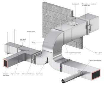
11.0 Air Conditioning – Ductwork Installation
11.1. Ductwork will be delivered from the fabrication area when required in a coordinated manner
11.2 Mark out support locations at duct work based on working drawings.
11.3 Drill holes in concrete element, fix anchors and drop rods.
11.4 Connect duct pieces in appropriate lengths and widths between support rods.
11.5 Lift and raise ducts from floor to support level manually for small sections or mechanically for larger sections.
11.6 Fix angle supports and nuts to support duct at correct level.
11.7 Correct more pieces in appropriate lengths and install at desired level
11.8 Connect adjacent duct sections by slip joints or angle flanges as specified with sealant or gasket as appropriate.
11.9 Fix necessary such as VCD’S. FDS. VAV’S access doors, veins and fans
11.10 Carry out pressure test to check for leakage monitoring with suitable instrument,
11.11 After approval of coordinated reflected full ceiling drawings commence installation of flexible ducts and air terminal devices.
12.0 Ductwork Insulation
12.1 After ducts have been satisfactorily tested for leakage insulation work will be carried out.
12.2 Clean the external surface of the duct to remove grease, moisture or deleterious material.
12.3 Apply specified adhesive to surface of ducts at the manufacturers recommended application rate.
12.4 Fix self-adhesive stickpins on spot welded pins at the specified intervals.
12.5 Cut and prepare insulation board pieces in required sizes according to manufacturer’s recommendations to prevent compression of insulation to less than 75% of its nominal thickness. Fix the same on the duct surface with the help of stickpins and previously applied adhesive, ensuring that the edges are straight and closely butted.
12.6 Fix the retaining speed washer on the stickpins / spotter pins.
12.7 Seal the joints and seams with vapour barrier mastic where required as per the specifications.
12.8 Seal the joints of insulation by aluminium foil adhesive tapes.
12.9 Apply the first coat of vapour barrier wrap with canvass/glass cloth and then apply second coat of vapour barrier.
12.10 Apply Insulation continuously through walls and partitions except fire rated walls and partitions.
12.11 For fire rated wall and partition penetrations, terminate insulation at fire damper sleeves.
13.0 Aluminium Cladding of Insulated Duct and Pipes
13.1 Cut the aluminium sheets of specified thickness to make boxes of the required size.
13.2 Between the surfaces of the canvas cloth, wrap on top of the insulation with brush.
13.3 Fit boxes of aluminum over insulated ducts and pipes.
13.4 Rivet on longitudinal and transverse blots and further if required with waterproof sealants.
14.0 Chiller Water Pipe Insulation
14.1 Ensure pipes are of correct specified type with appropriate documentation and certification.
14.2 Remove end caps, clean and paint with red oxide.
14.3 Drill holes in concrete slab and fix anchors and drop rods and per approved working drawings.
14.4 Fix pipe hangers and install pipes.
14.5 Pipe connections may be either welded or flanged and belted dependent on the specification.
14.6 For welded pipes approved welder will be used.
14.7 Fix valves in pipes.
14.8 Carry out pressure testing of the pipe.
14.9 After successful pressure testing carry out insulation / cladding work.
14.10 Prior to testing and balancing of chilled water system, treat pipe with recommended chemicals and flush with water.
15.0 Plumbing
15.1 During the foundation and concreting stage of the civil works, suitable approved sleeves will be provided in the beams, slabs and columns. The underground drainage work will be carried out simultaneously with the progress of the civil works. Proper slopes will be maintained and the pipeline will be checked for water tightness by subjecting the pipes to required pressure as given in the contract documents. All the drainage pipe work in the horizontal run will be supported.
15.2 Adequate traps will be provided with water seal. Pipeline passing through fire barriers will have fire-stopping sleeves. Standard method of construction as specified In contract documents will be followed, Special care will be taken for safely aspect during execution.
15.3 During installation and handing pipe and things will be closed by arid caps to avoid the ingress of dust and dirt.
15.4 Plastic pipes will be stored in a covered area to avoid deterioration due to exposure to UV sunlight.
15.5 Installation levels will be taken as those defined in the drawings and specifications of the construction contract.
15.6 A check will be made with the municipality or statutory authority for their relevant level system arid benchmark to ensure coordination with the discharge drainage.
15.7 Buried pipe work will be carried not in coordination with the external civil works.
15.8 A review of all the contract drawings will be made to ensure proper slopes are specified.
15.9 External installation connections to municipal drainage department will be offered tor inspection by the relevant authority.
15.10 Adequate clean out and traps will be provided unless specified elsewhere in the contract.
15.11 Copper pipes will be joined by the silver brazing method arid tasting of joints will be carried out In accordance with the contract.
15.12 Prior to delivery and installation of sanitary ware a trial mock up installation will be prepared and offered for review and approval by the consultant and CONSULTANT.
15.13 All fire fighting installation will be submitted far approval by the civil defense department and water supplied pipe will be flushed and disinfected in accordance with the contract requirements.
16.0 Electrical Works
The program for the sequence and coordination electrical and construction work activity will be based on the main activities shown below:-
16.1 Electrical Activities
- Lay underground ducts or sleeves.
- Place sleeves / box outs in concrete slabs.
- Fur conducting DB and outlet boxes in wall recesses.
- Surface conduit.
- Fix shade or cable trunking.
- Fix surface DBS and SMDB’s.
- Install wiring, cabling & power cabling.
- Install suspended ceiling.
- Fit surface lighting fixtures.
- Fix UPS.
- Fix fire alarm devices and wiring accessories.
Fix recess light fixtures
- Fix lighting control system.
- Install bus bars.
- Install MDB’s.
- Install OG sets & associated works.
- Install transforms and HT cabling.
- Install earth pits.
- Testing.
16.2 The installation of electrical equipment is briefly summarized below:
- Underground sleeves for electrical services will be commenced during the earthwork and ground preparations.
- Concealed conduits, sleeves/ducts etc. in the slabs and walls will be installed during the slab concreting and wall construction i.e. block work.
- Cable support systems which includes the cable trays, trunking etc. installation will commence after the slabs are ready and in coordination with the other services i.e. Mechanical, Plumbing and Fire Fighting.
- DB’s SMDBs and MDBs installation will commence after the designated walls and electrical rooms are complete in almost air respect of dell activities.
- Circuit wiring and cabling work is carried out after the completion of structural and block work including the plastering.
- Installation of lighting fixtures, FA system and ELV equipment will be after completion of the painting activity.
- External works including earthing, lightning protection and external lightning will commence with the preparation of landscaping and roadwork.
- All the above works are to be inspected by the concerned authorities immediately after completion of each activity to ensure that all the specifications are complied during the installation and the installation is carried out as per the manufacturer’s guidelines.
- Testing will be carried out progressively after each activity. Final testing will be carried out prior to handover.
- Initially, the Consultant will carry out inspection testing and this will be followed by Inspection by the local power authority.
- Incoming power supply by the local power authority (the service connection) will be given when the latter completes the associated works.
Discover more from Project Management 123
Subscribe to get the latest posts sent to your email.