This method statement covers the procedure involved in handling and installation of underground GRP/FRP piping in a trench.
The purpose is intended to assist the client, customer/ installer in understanding the requirements for the successful GRP pipe handling and installation. The recommendations given in this plumbing method statement are easy to follow and implement.
This procedure provides details for underground pipe installation in soil conditions as prevalent in the project area, the type of installation shall be proposed based on the site conditions and terrain in the project area.
Transportation and handling of GRP/FRP Pipes
From the laydown area to the trench site, the pipes shall be transported through trailers.
Spreader bars may be used when multiple support locations are required.
Prior to unloading of pipes from trailers, all items shall be inspected for any visual / transportation damages.
Single pipes must be unloaded and handled separately (one at a time).
Use pliable straps, slings or ropes to lift single pipes.
Do not use steel cables or chains to lift or transport the grp pipe.
Pipe sections can be Lifted with only one support.
Care shall be taken to prevent pipes from rolling or falling from flat bed trailer, this shall be attained by using proper supports, chocks.
If at any time during handling or installation of the pipe, any damage such as cracks, delamination or fracture occurs, the pipe should be repaired before the section is installed.
Contact supplier for inspection of damage and for recommendation for repair method or the replacement.
Rubber gaskets received along with the pipes and fittings shall be stored in Shelter with original packing until it is used at site.
The gaskets must be protected from exposures to grease or oils, which are Petroleum derivatives, and from solvents and other deleterious substances.
Lubricant is special vegetable soap (free from grease / petroleum products), only this lubricant shall be used.
Handling of Nested GRP Pipes
It is proposed to nest various diameter pipes during transportation.
Always lift nested bundles using at least two pliable ropes.
Always keep nested pipes on site in the original transporting package only.
Stacking of these pipes is not advisable.
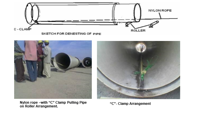
De-nesting of pipes should be done carefully at pre allocated station.
Inside pipe may be removed by lifting it slightly with an inserted padded boom to suspend the section & carefully move it out without damaging the outer pipe.
Storing & Stacking of GRP/FRP Pipe
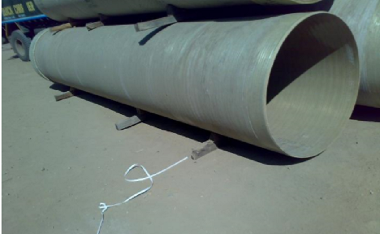
The grp pipe can be stacked easily, with small precautions.
Ground area should be relative flat & dry, free of rocks or any other potentially damaging debris.
Place flat timber supports as four meter spacing, to facilitate placement & removal of lifting slings around the pipe & Stack the pipes on them.
Make sure that the stack will be stable for condition such as high wind, unlevel storage area or other horizontal loads.
Maximum stack height is approximately three meters.
Stacking of pipes larger than 1400 mm diameter is not recommended.
Rubber ring EPDM gaskets, being shipped separately, should stored in shade in their original packaging and should not be exposed to sunlight, except during the pipe jointing.
The gaskets must be protected from the exposure to grease & oils, also from the solvents & other deleterious substances.
Pipes Preparation at site storage area:
It is convenient and more practical to fix one coupling at each pipe end prior to lowering it into the trench.
Following is the method to join the coupling:
Clean the coupling thoroughly from inside, specially the internal groove, from dirt, grease or any material deposition.
Insert the gasket into the grooves, leaving two or more uniform loops of rubber (depending on pipe diameter) extending out of the groove.
Do not put any lubricant in the coupling grooves or on the gasket at this stage.
There should be a minimum of one loop for each 450 mm of gasket ring circumference.
With uniform pressure, push each loop of the rubber gasket into the gasket groove.
When installed, pull carefully on the gasket in the radial direction around the whole circumference to check for well-distributed compression of the gasket.
Apply lubricant on gasket that will facilitate easily fixing of coupling to the pipe.
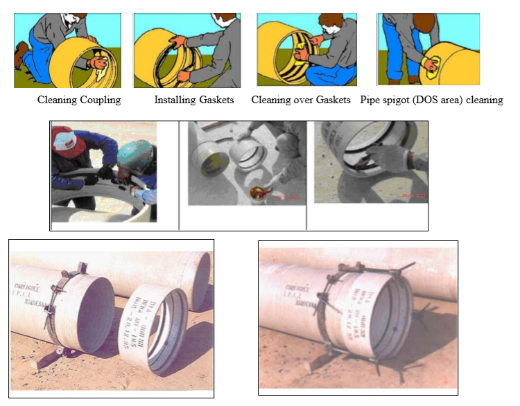
Also, apply a thin film of lubricant on pipe spigot (DOS area) & align the coupling with pipe.
Never use a petroleum based lubricant for FRP pipe Jointing.
Fix a cross bar on the coupling face.
Use two nylon slings & fix the come-along jacks (pullers) at each side of the pipe spring line.
The puller capacity shall be 3 to 5 tons range.
Ensure that the coupling & pipe is aligned.
Start tightening the puller from both ends same time.
The coupling will insert the pipe spigot gradually.
Make sure that the black home line marked on the pipe is matching equally in circumference.
Loose the pullers & move to other coupling.
BED & Pipe Zone Backfill Materials
Most coarse-grained soils, (gravel, crushed stone, good clean murrum and sand) are the recommended bedding & pipe zone backfill materials.
Gravel is easier to compact than sand and allows the pipe to be installed deeper, if required.
Use of Native Soils
Where native soil is used as pipe zone backfill, the following restrictions apply:
a) No rocks greater than maximum gravel size
b) No soil clumps greater than 2 times the maximum gravel size.
c) No organic material.
d) No debris (tires, bottles, metals, etc.).
Where compaction is specified: the native soil must be granular in nature.
Pipe Bedding
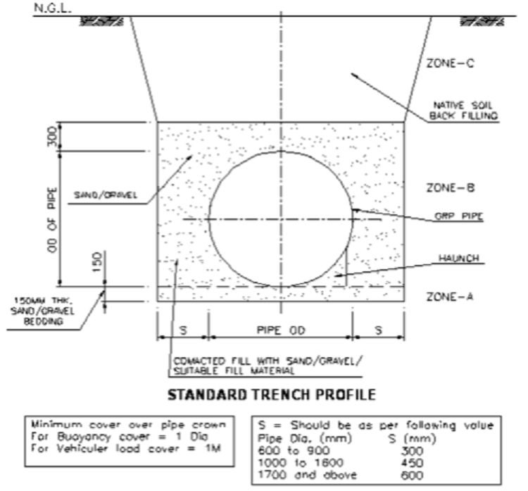
Pipe bedding material shall be sand or gravel in accordance to the requirements.
The bedding shall he placed after the trench bottom is compacted to provide proper support.
Minimum compaction of the bed shall be 90% Standard Proctor Density (70% of maximum relative density for crushed rock, crushed stone or gravels).
The bed must be over-excavated (manual digging is enough) at each coupling joint location to ensure that the pipe will have a continuous support and does not rest on the couplings.
However, this area must be properly bedded and backfilled after the joint assembly is completed.
Pipe Jointing in the Trench
Position the crane near the trench (safe distance).
Unload the pipe and place into the trench.
Make sure that the bedding is mechanically compacted prior to pipe laying as per the required specification.
After placing the first pipe bring the second pipe near the pipe placed and install it (by pulling to chain) with clamps, chain blocks/pullers as shown in the recommended manufacturer procedures or as below diagrams.
Backfilling the GRP Pipe:
When gravel or crushed stone is used as backfill, immediate backfilling after joining is desirable, as it will prevent two serious hazards, floating of pipe and thermal movements.
Floating of pipe can damage the pipe and create unnecessary reinstallation costs, this may not be the case in a project where the water table is not encountered.
Thermal movement caused by exposure to the elements can cause the loss of seal due to movement of several lengths acting on one joint.
Proper selection, placement, and compaction of pipe zone backfill are important for controlling the vertical deflection and are critical for pipe performance.
Attention must be paid so that the backfill material is not contaminated with debris or other foreign materials that could damage the pipe or cause loss of side support.
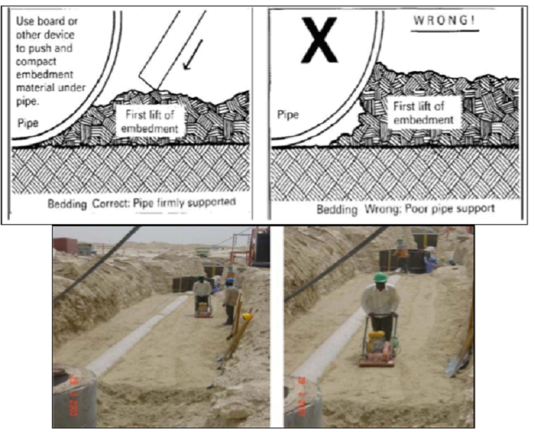
During backfilling, the granular material should flow completely under the pipe to provide full support.
A blunt tool may be used to push and compact the backfill under the pipe.
Proper backfilling should be done in 150 mm to 300mm lifts depending on backfill material and compaction material, 300mm lifts will be adequate since gravel is relatively easy to compact.
Sand needs more compaction efforts.
The compaction of sandy backfill is most easily accomplished when the material is at or near its optimum moisture content.
When backfilling reaches pipe spring-line, all compaction shall be done first near the trench sides and proceeds towards the pipe.
It is recommended that placing and compacting of the pipe zone backfill is done in such a way as to cause the pipe to ovalize slightly in the vertical direction.
Using Thrust blocks
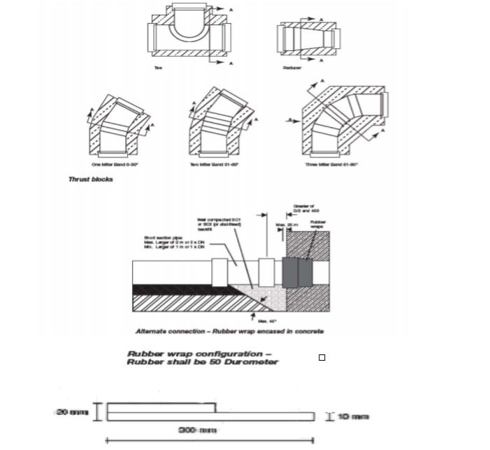
RCC thrust blocks will be constructed (common thrust blocks for all pipes including product lines) at the places of bends, tees & reducer.
It is recommended to wrap a band of rubber around the pipe prior to placement of any concrete.
Rubber should protrude (25 mm) from the pipe.
Rubber thickness 10 mm & of 50 Durometer hardness.
Drawings as given by manufacturer will be used for construction.
It is always recommended to cast thrust blocks as laying progresses.
Before the hydrotest all thrust blocks should be completed.
It is always recommended to have coupling on two edges when pipe comes out of thrust block.
Immediately after thrust blocks, provide one small pipe piece (1 to 2 meter length) with coupling on each side of block to take care of uneven settlement.
Buoyancy Control Requirements
Minimum cover required on pipe crown to avoid upliftment of empty pipes in high water table areas is one meter or one diameter which ever is more.
If sufficient cover is not available and the area has the possibility of high water table RCC precast blocks or insitu blocks of required weight are to be used to counteract unbalance uplift forces.
River/ Nalah crossing/ road crossing
Encase the pipe min 300 mm all around with M20 grade concrete & balance portion of the trench should be backfilled with crushed rock preferably.
The minimum backfill cover on the pipe should be 1.5 meter.
Backfill here should be type SC1 preferably up to the ground level.
Concrete Encasement:
When pipes (or fittings) must be encased in concrete such as for thrust blocks, stress blocks, or to carry unusual loads, specific additions to the installation procedures must be observed.
Flooded Trench Treatment Requirements
When the ground water table is above trench bottom, the water level must be lowered to at least the trench bottom (preferably about 200 mm below) prior to preparation of the bed.
Different techniques may be used depending on the nature of the native material, for sandy and silty soils a system of well point to a header pipe and a pump is recommended.
The spacing between individual well point and the depth at which they will be driven depends on the ground water table and the permeability of the soil.
It is important to use a filter around the suction point (coarse sand or gravel) to prevent clogging of the well-point by fine grained native material.
When native material consists of clay and bedrock, well-point will not work.
Dewatering is more difficult to achieve in this case, the use of sumps and pumps is recommended.
If the water cannot be maintained below the top of the bedding, subdrain must be provided.
The subdrain should be made using single size aggregate (20 -25 mm) totally embedded in filter cloth.
The depth of the subdrain under the bed depends on the amount of water in the trench.
If the groundwater can still not be maintained below the bed, filter cloth should be used to surround the bed (and if necessary the pipe zone area as well) to prevent it from being contaminated by the native material.
Gravel or crushed stone should be used for bed and backfill.
The following cautions should be noted when dewatering:
Avoid pumping long distance through the backfill material or native soil, which could cause loss of support to previously installed pipes due to removal of material or migration of the soil.
Do not turn of the dewatering system until sufficient cover depth has been reached to prevent pipe flotation
Post installation checks:
Checking the installed pipes: Procedure for checking the initial diametrical deflection for installed pipes:
- Complete backfilling of grade.
- Complete removal of temporary sheeting (if used)
- Turn off the dewatering system (if used)
- Measure and record the pipes vertical diameter.
- Calculate vertical deflection
Deflection % = Actual I.D. Minus Installed Vertical I.D. x 100 / Actual I.D.
Deflection checks should be done when the first installed pipes are backfilled to grade and continued periodically through out the entire project.
Laying shall not get too far ahead before verifying the installation quality.
This will ensure early detection and correction of inadequate installation methods.
Pipes installed with initial deflections exceeding the value given as above, shall be reinstalled so that the initial deflection is less than the stated values.
Correcting Over Deflected Pipe:
Pipes installed with initial diametrical deflections exceeding the values shall be corrected to ensure the long term performance of the pipe by re-excavating the re-backfilling with proper case.
Procedure:
Excavate near the pipe invert / haunch depth.
Excavation just above and at the sides of the pipe should be done utilizing hand tools to avoid impacting the pipe with heavy equipment.
Inspect the pipe for damage. Damaged pipe should be repaired or replaced.
Recompact haunch backfill, ensuring it is not contaminated with the native soil.
Backfill to grade and check the pipe deflections to verify they have not exceeded the values as specified.
Correction Over –Deflected Pipes
Pipes installed with diametrical deflections exceeding the value in the specifications/table must be corrected to ensure the long- term performance on the pipe.
Procedure For pipe deflected up to 8% of diameter:
Excavate down to the haunch area, which is approximately 85% of the pipe diameter.
Excavation just above at the sides of the pipe should be done utilizing hand tools avoid impacting the pipe with heavy equipment.
Inspect the pipe for damage. Damaged pipe should be repaired or replaced.
Re-compact haunch backfilling, making sure that it is not contaminated with unacceptable backfill material soil.
Re-backfill the pipe zone in lifts with the appropriate material, compacting each layer top required relative compaction density.
Backfill to grade and check the pipe deflection to verify they have not exceeded the initial values in given table.
For pipe deflected greater than 8 % pipe diameter:
Pipes with over 8 % deflection should be replaced completely.
Cautions:
Do not attempt to jack or wedge the installed over-deflected pipe into a round condition.
This may cause damage to the pipe.
If excavating multiple pipes, care must be taken to not mound the cover from one pipe over the adjacent one.
The extra cover and reduction of side support could magnify an over deflected situation.
Discover more from Project Management 123
Subscribe to get the latest posts sent to your email.