This Method Statement covers the installation of uPVC and HDPE pipes for use with the underground and substructure drainage piping systems.
Procedure defines the method used to ensure the underground drainage pipework installation has been carried out as per technical specifications and best commercial and engineering practices.
Roles & Responsibilities
Project manager will be overall responsible for complete MEP works.
MEP Site Engineer will be responsible:
To ensure that all the preparation and application works are carried out according to the contract specifications and manufacturer’s data sheet(s).
Ensure that the progressing of works is carried out according to the planned program, and as per the approved method.
To ensure that all the equipment and material required in executing the work are available according to the planned construction program.
To coordinate with the main contractor’s MEP coordinator and safety officer for all safe and proper execution of the works in accordance with the risk assessment.
To coordinate with the civil engineer for required access arrangements
MEP Foremen will be responsible:
- To guide and control the tradesmen and charge-hand(s)
- Ensure that work is done as per the approved shop drawing(s)
- Report all matters to the MEP site engineer.
Safety Engineer will be responsible for implementation and assurance of safety and environmental requirements (JSEA)
Quality Control Engineer will be responsible for the implementation of the relevant method statements, ITP and checklists.
Plant, Equipment and Welfare Arrangements
Plant and Equipment: Plumber’s Toolbox, Helper’s Toolbox, Hack saw, File, Bristle brush, wrench, measuring tape, portable communication device (mobile phone), Water Tanker, Wheel Loader, Boom Loader and Electro-welding machine
The minimum Personal Protective Equipment (PPE) on site is:
- Hard hat
- Safety boots
- High-visibility vest
- Gloves
- Goggles/Glasses
Health Safety Welfare & Emergency Requirements
Toilets are located at site cabins, No other facilities will be used.
Chilled drinking water stations are available on site.
No food or drink is permitted on working area on Site.
Smoking is permitted only in the compounds.
Minor injuries will be taken to the site clinic for the site nurse to deal with.
Major injuries will be taken directly to nearest hospital
All incidents are to be reported directly to the Site Safety Team
Any vehicles that are leaking any substance are not to be used for soil movement.
All operatives will attend the Project Safety induction prior to commencing work on site.
As a minimum a Daily Briefing will explain and discuss:
- what the day’s work is for the gang and individuals
- planned sequence of work
- plant requirements
- materials requirements
- trades handing over I handing back
- other trades and their work in the vicinity
Sequence of Work for Drainage Piping Works
Delivery, Handling and Storage
The material supplied shall be packed for protection against damage during handling, transport , warehousing and installation.
Protect stored pipes and tubes from moisture and dirt. Elevate above grade. Do not exceed structural capacity of floor if stored inside.
Protect fittings and piping specialties from moisture, dirt and dust.
All pipe material and fittings are to be stored in a safe and shaded area. Upon arrival on site, none of the material is to be exposed to sunlight.
Material to be stored as per manufacturer’s instructions.
All fittings to be segregated as per type and size, and protected properly.
All materials to be accounted for.
Supports to be provided to prevent sagging / bending.
Inspection of Materials in Store
Notify MEP Engineer upon delivery of material at site.
Upon the receipt of materials on site, these shall be inspected by the QA/QC Engineer / Inspector to ensure correctness of material as per the approved material submittals and quantities.
Ensure that the materials are handled properly as per the manufacturer’s stock piling requirement, and protected against dust, dirt and foreign matter.
A material inspection report shall be prepared by QA/QC Engineer/ Inspector for submission to the consulting engineer for review and acceptance.
Pre-installation Checks
Ensure that “Notification to Start Activity” had been issued to the Consultant.
Check and make sure that the installation area is clean from debris and foreign matter.
Ensure that materials selected are as per approved Material Submittal.
Check that adequate number of tradesmen and proper tools are present.
Ensure that latest approved shop drawing for this installation is present, and all personnel are working using the same drawing.
The Site Supervisor shall review the layout drawings and ascertain that all necessary right of ways and trenching permits are obtained.
In case of embankment fill, the pipe excavation may not be started unless the embankment is formed / executed for at least 300 mm above the crown of the pipe and/or up to the formation if necessary.
Subsequent to the above survey setting out to the approved location, design profile, number of ways shall be carried out on site and approved by the consultant.
Installation of HDPE Drainage Pipes
As well as laying the pipes, the procedure also demonstrates the method of electro-welding. The testing of the pipes will be done prior to backfilling, testing methodology is stated in below sections.
Electro-fusion welding and coupling equipment shall be supplied directly from manufacturer. Piping and joint in the shop to be fabricated in controlled environment when practical to ensure proper alignment and welding of pipe.
The manufacturer shall provide training for HDPE pipe jointing. The personnel operating heat fusion joining equipment and on-site joint inspector shall be trained by manufacturer or manufacturer’s authorized representative.
Fusion equipment and operator shall be required to demonstrate successful field experience.
Jointing of HDPE Pipes
The method adapted for joining shall be approved by the pipe manufacturer/supplier. Welding of the piping works will be certified by an agency and according to the quality welding procedure.
Prior to the fusion welding, the pipes are to be held in place by supports/brackets to allow for accurate welding.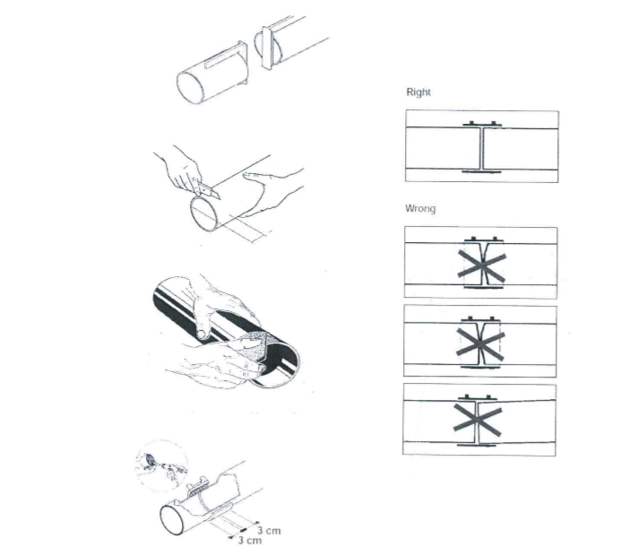
The following is the method that will be employed to join the pipes:
Preparation
Cut Pipe Square
Dry, Clean, Scrape welding ends.
Remove burr. Welding ends must remain dry during the whole welding process.
Electro Welding of HDPE Sleeve Coupling
Insert pipe or fitting ends into the sleeve coupling.
Connect electro-welding machine, start welding procedure. Welding time approx. 70-90 seconds.
Note: Electro weld sleeve couplings should not be welded twice. However, in exceptional cases a repetition can be done, but wait at least 1 hour until the socket has completely cooled down.
Jointing of uPVC Pipes
Preparing the Pipes
Before installation, each pipe and fitting should be inspected to see that its bore is free from foreign matter and that its outside surface has no large scores or any other damage.
All the pipe ends should be checked to ensure that the spigots and sockets are free from damage.
Pipes of the required diameter and class should be identified and matched with their respective fittings and placed ready for installation.
Push Fit type Jointing Method
The elastomeric sealing ring locates positively within the socket groove permitting easy entry of the spigot while ensuring a pressure-tight seal under all working pressures.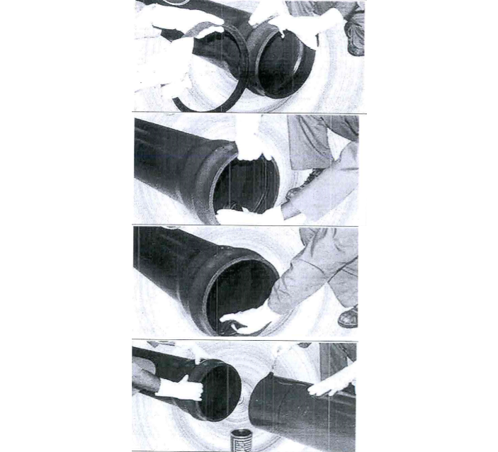
Carefully examine and clean the spigot, rubber sealing gasket and the inside surface of the socket.
Form a loop and insert the rubber gasket with the thickest edge towards the inside of the pipe.
Allow the gasket to seal evenly around the groove. Press down on the remaining portion of the loop to finally place gasket evenly into position.
Lubricate the chamfered end of the pipe by a minimum of half the spigot length.
Push the spigot of one pipe into the socket of the other up to the home line after making sure that the pipes are aligned both in horizontal and vertical planes. Marking on the spigot of pipe shall be done at least 1- to 2 cms from full length of socket so as to maintain gap for expansion / contraction.
Laying of the Drainage Pipes Below Grade
Excavation, compaction and backfilling will be undertaken by the civil contractor and as per the specification section about the earthwork.
Before laying, all pipes and components will be checked for defects and joint.
The trenches shall be checked and proven for the width and depth as per the trenches section drawing prior to the laying of pipes.
Ensure sand bedding as per the approved shop drawing is provided in the trench, before laying the pipe, at slope of 45 degrees as per procedure for checking and laying pipes at exact invert level and in coordination with other services.
Ensure enough space is provided underneath the pipe joints for easy access of jointing the pipe.
Before lowering, the pipes in trench ensure that trench has been inspected, cleared for pipe laying and approved by Engineer as per procedure for making / marking of supports and invert level.
Pipes laid in trenches will be provided with a solid uniform bearing throughout their entire length and as per manufacturer’s recommendation. Pipes to be laid with marked side up for identification.
Pipes will not be buried at less than 60 cm below finished grade for protection against mechanical damage.
All pipes will be laid to a uniform slope as indicated on approved shop drawings.
After successful completion of installation and leak, slope and hydro tests approved by consultant, backfill the trench as per approved shop drawings and as per manufacturers recommendation.
Final back filing shall be carried out as per the approved backfilling method statement.
Flexible joints will be made in strict accordance with manufacturer’s instruction and to ensure movement of joint.
Concrete fill will be laid by civil subcontractor in 100 mm layers and compacted to a level 300 mm minimum above top of pipe followed by main backfill material.
Provide warning tape above pipe work 300 mm prior to backfilling as approved.
Installation of Pipes within Structural Slab
Prepare supporting chairs tied to structural reinforcement bars.
Wrap pipe with neoprene protection fabric at all supports.
Adjust chairs to provide correct drainage falls.
Test as per below given procedure.
Installation of Cleanouts on Soil and Vent Pipes
Cleanouts will be installed at each change of direction of drainage pipes, greater than 45 degrees, inside the building as per the approved shop drawings or every 15 meters for horizontal straight pipes where indicated on the approved shop drawings.
Cleanout will be provided at or near the foot of each vertical waste or soil stack.
The cleanouts on concealed piping will be extended through and terminate flush with finished wall or floor.
Cleanouts will be of the same nominal size as the pipes up to 100 mm pipe diameter and not less than 100 mm for larger piping.
Refer to the approved shop drawings for laying of the pipes at the correct invert levels.
Pipelines on Steep Slopes
Two problems can occur when pipes are installed on steep slopes, i.e. slopes steeper than 20% (1:5).
The pipes may slide downhill so that the witness mark positioning is lost. It may be necessary to support each pipe with some cover during construction to prevent the pipe slipping or other appropriate method as per the approved shop drawings.
The generally coarse backfill around the pipe may be scoured out by water movement in the backfill. Clay stops or sandbags should be placed at appropriate intervals above and below the pipe to stop erosion of the backfill. Where bulkheads are used, one restraint per pipe length placed adjacent to the socket, is considered sufficient for all slopes.
Testing of Drainage Piping System
The drainage system will be tested for leakages before encasing in concrete.
Warning barriers shall be erected around the test area.
All test points will be plugged shut with test plugs.
It will be ensured that all bends, changes of directions and ends of run are restrained against movement as water exerts a thrust force equal to static pressure times the area. This thrust can dislodge joints if not properly restrained . A temporary test stack of 30KPa (3m) height will be installed at the desired test point (highest point).
Marking to be done outside of stack if stack is of bigger length.
Water will be filled into the system slowly through the test stack, allowing the air trapped inside the pipe to escape. Failure to remove this air will cause faulty test results.
The water shall be filled to the full height of test stack and the joints shall be inspected after minimum 60 minutes to assess if any water leakage has taken place. Top of stack to be covered to avoid anything falling inside.
If any water leaks are found, the joint shall be disassembled and inspected to determine if the correct procedures were followed.
Hydro test shall be repeated after rectification of any leaks.
The pipe will be filled with water and allowed to stand for 8 hours, consultant is invited to inspect the installation and testing.
After approval from consultant, the encasement for the drainage system shall be done prior to backfilling.
Inspection Checklist for Drainage Piping Installation
Checking of existing ground levels.
Mark the routing of pipe work.
Inspection of formation of level including compaction.
Check pipes, fittings & accessories used have an approved material submittal.
Ensure that shop drawings are approved for construction.
Check that trench has been cleared for pipe laying.
Inspect and check that the pipes have been installed as per approved shop drawing.
Check the installation prior to back filling.
Backfill the pipe partially except the joints.
Water or hydrostatic pressure test as per specification.
Check for any sign of leaks.
Encasing of pipe after test completed.
Discover more from Project Management 123
Subscribe to get the latest posts sent to your email.