Below is a precise electrical method statement that explains step by step procedure high voltage underground cable installation.
By following this cable laying procedure installer shall ensure that the job execution complies with the project requirements and serves the intended function to satisfaction of the client.
Overall project manager is responsible for implementation of this high voltage cable installation methodology.
Required Tools For HV Cable Installation
- Fork Lift or Crane, pallet mover with capacity & arrangement in line with the Manufacturer’s, recommendations and as required at site
- Portable hand tools
- Portable Drilling Machine/ Grinding Machine & Angle Cutter
- Spirit Level
- Digital multimeter
- Megger 5 kv
HANDLING & STORAGE OF HV CABLES
On receipt of the HV Cables and accessories at site, necessary precautions shall be taken for unloading, shifting & storage, as follows:
- Material shall be stored in a covered / dry space at all the time inline with manufacturer’s recommendations.
- Cable / Cable Drum received at site will be inspected to find out any kind of physical damage to HV cable.
- All materials received at site shall be inspected to make sure these are as per approved material submittals.
- Any discrepancies and/or damage found will be notified to supplier and reported to management for further action.
- Material found not suitable for site use will be removed from site immediately.
PRE INSTALLATION PROCEDURE FOR HV CABLES
Prior to start the installation of high voltage cables, refer to the approved shop drawings related to the area of installation and ensure that required materials are available at site as per approved material submittals, drawings and cable schedule.
Ensure the materials were stored properly and there is no mark of damage or deformity of any kind before issuing the material from site store.
The cable drum will be inspected prior to shifting to site for any mechanical and structural damage during transportation.
Ensure the installation of HV Cables are carried out in accordance with manufacturer’s and local authority installation recommendations, requirement of applicable standards and in accordance with recognized industrial practices and specified in project specification to ensure that installation complies with requirements.
INSTALLATION PROCEDURE FOR UNDER GROUND HV CABLES
The total cable route shall be inspected to ensure that the routing is complete, as per approved layout and free from any sharp edges or objects.
Make sure the route for high voltage cable installation is coordinated with other external services.
Size and length of the cables to be checked by the Engineer In charge and Supervisor before cutting the HV cables. As per cable cutting schedule, site electrical supervisor will ensure that the cable drums are shifted to the required locations.
Cable drums are to be positioned on jockeys and cable end to be left from the top.
Rollers are to be placed in regular intervals according to cable route while pulling the cables, dragging/rubbing of cables on ground shall be avoided to protect the cable insulation.
HV cable laying shall start by rotating the drum in direction recommended and marked on side of the cable drum, cables are pulled, accordingly.
Insulation resistance of HV Cable should be checked by using 5 kv megger after installation and before termination of cables, all the readings shall be noted on approved reports and submitted to the consultant.
The width of the HV cable trench shall be maintained minimum 800 width and 1000 mm depth according to the number of cables for buried cables.
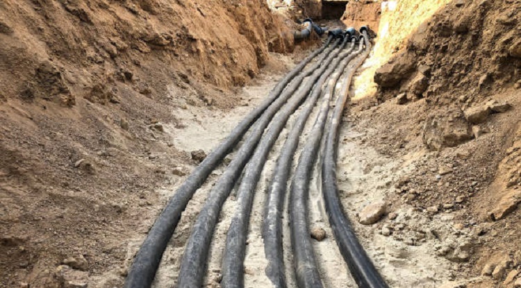
The high voltage electrical cable is laid in a trench.
Soft sand shall be spread 150mm below the cables and 100mm above the cables. Over this a layer of 300mm clean earth shall be filled. Each layer of 100mm need to be softly Rammed.
Concrete tiles should be laid above the clean earth layer before closing the cable trench.
Also install a HV cable marking tape 250mm below the finished ground level covering each cable.
Install a cable marker at each change in cable direction, joint position and entry points to buildings.
High Voltage cables installed in ground shall be laid in a single, horizontal layer spaced 450mm apart.
Obtain Consultant’s approval before cables are covered and trenches are backfilled.
All cables shall be installed with approved identification bands at each end and over their entire length at 30 meter intervals.
HV cable termination should be done as per approved specification and by authorized / certified technician under the supervision of electrical engineer in charge.
Before and during the high voltage cable installation site engineer / site supervisors should ensure the approved shop drawings of latest revision are followed and approved materials are used for installation.
INSTALLATION PROCEDURE FOR HV CABLES ( IN TRAY )
The total cable route shall be inspected to ensure that the routing is complete, as per approved layout and it is coordinated with other services.
Size and length of the cables to be checked by the engineer incharge and Supervisor before cutting the HV cables, as per cable cutting schedule.
Cable drums are to be positioned on jockeys and cable end to be left from the top.
Rollers are to be placed in regular intervals according to cable dia while pulling the cables and rubbing of cables on ground shall be avoided to protect the cable insulation.
Cable laying shall be started by rotating the drum in a direction recommended side of the cable drum and cables are pulled carefully.
Insulation resistance of HV Cable should be checked using by 5 kv megger after installation and before termination of cables and readings shall be submitted to the consultant approval.
The trays shall be curved enough at the right angles to allow the cable to pass with correct bending radius.
Where more power cables are run together, adequate cable tray should be provided considering the spacing as per specification, spaced apart by at least one cable diameter (of larger cable) throughout the length of the cable run.
Cables shall be identified at the both ends by identification bands as per approved materials and approved cable schedule.
HV cables shall be dressed properly, secure cables to cable tray using cleats where the cable is fixed to a vertical cable tray or ties where the cable tray surface is horizontal without any overlapping and it will be ensured that the cable distance is maintained as per approved shop drawing.
Earth conductor shall be laid parallel along with cables.
Where cable passes through a floor or fire barrier, fire stopping material should be provided and that area should be sealed properly from both sides.
On completion of HV cable laying and dressing on trays and ladders, continuity and insulation resistance tests with ( 5kv) Megger shall be carried out and shall be recorded for consultant approval.
Cable ends shall be earthed and sealed properly.
All conductors requiring bolted connections shall be terminated with compression lugs, using an automatic compression crimping tool.
Cable lugs shall be tinned copper compression heavy duty type.
Terminations of hv cable shall be carried out as per standard and approved procedure.
Wiping type cable glands to be used of approved quality as per standard size.
All test result shall be submitted after meggering of the cables.
Crimped terminations shall be used for cables and pinch screw should not be used.
HV cable termination shall be carried out as per approved drawings.
Earthing of HV Cable shall be done as per local authority regulations, specifications and approved drawings.
After inspection of HV Cable and approval by authority and Consultants, proper care will be taken to protect them from dust by suitable covering until released for the testing commissioning work and final handing over to client.
Discover more from Project Management 123
Subscribe to get the latest posts sent to your email.