The purpose of this plumbing method statement is to define the procedure for the preparation and construction of gravity sewer lines with GRP pipes with associated inspection chambers, manholes in accordance with the requirements specified in the relevant specifications 0considering safety and quality of the work activities.
Scope of work may cover any length of the gravity sewer lines and manholes associated with house/building connection chambers to facilitate the project.
The pipeline is connected to gravity feed connection to the pumping station adjacent to project boundary.
The G.R.P pipes 150mm diameter, 200mm dia. and 300mm dia. are laid in trench width of 600mm + pipe diameter in a stable soil and 5 times pipe diameter in unstable soil.
Definitions and Abbreviations
Engineer – Representative of engineering consultancy company
ICL: Inspection Check List
IR: Inspection Request
ITL: Independent Testing Laboratory
ITP: Inspection and Test Plan
ITR: Inspection & Test Requests
MAT: Material Submittal
MEP: Mechanical Electrical Plumbing
MET: Method Statement
MIR: Material Inspection Request
MSDS: Material Safety Data Sheet
PPE: Personal Protective Equipment
PQP: Project Quality Plan
PTW: Permit To Work ( Working at Height or enclosed/confined spaces)
RA: Hazard Identification and Risk Assessment
RFIA: Request for Inspection and Approval
SPD: Shop Drawing
TBM: Temporary Bench Mark
Roles and Responsibilities
Project Manager
To ensure that the subject works are done in coordination with other works with the requirements of Quality Plan & program.
Ensuring the full compliance of subcontractors with Company Quality policies and with the requirements of this method statement.
To ensure that all the equipment required to execute the sewage works according to the construction program are available, in good condition, and provide any additional equipment that might be required.
Co-ordinate with the construction Manager, Project Engineer, Safety Engineer, Foreman and Surveyor for a safe and proper execution of the works.
To guide specific attention to all measures in coordination with the safety Officer/Engineer.
Site Engineer
Ensure area is ready and safe to start the works.
Arrange the required Plant manpower & Equipment’s in coordination with Project Engineer / Site Foreman.
Liaise and co-ordinate with the Project Manager to execute the works as per approved drawings.
Coordinate with safety officer to maintain safe working & proper housekeeping of construction site all the time.
Project Engineer
The Project Engineer will carry out his duties in a manner that will be coordinated by the Project Manager on a daily basis, and will ensure proper distribution of construction groups.
To be aware of test frequencies related to the drainage piping installation activities.
Control the disposal of waste excavated material according to the instructions received from the project manager.
To inform the QC Inspector of the areas ready for inspection and to prepare the RFIA with complete attachments.
QA/QC Engineer / Inspector
Ensuring that Consultant/Client inspection requests are implemented.
Compilation of all necessary quality control checklists and test reports.
Assisting Consultants during the site inspections.
The control of work performance by means of checking the work before consultants’ inspection and issuing RFIAs & punch lists as necessary.
Completion of documentation to verify the work is performed in accordance with project requirements.
Controlling all inspection activities on-site in line with ITPs.
Ensuring that all test equipment including surveying equipment is calibrated and is suitable for use on-site.
Surveyor
To establish benchmarks from agreed reference points, provide required setting out and level markings and follow up with regular checks.
Co-ordinate with the Site Engineer / Foreman and ensure the approved shop drawings/construction drawings will be implemented properly.
Maintain survey details and reports, periodically check the progressing works and advise the Project Manager of any deviation from the drawings.
HSE Engineer/Officer
Ensure implementation of all safety measures related to the nature of works being carried out, and in accordance with the Project HSE Safety Plan.
To ensure that all the persons involved in the drainage and sewage works are aware of their responsibilities, and that they have enough understanding of the safety procedures.
The safety officer will report directly to the Project Manager, who will ensure that all the recommended safety measures are implemented and maintain safe working on the site.
To maintain continuous inspections of the site activities, advise and train persons on a daily basis to prevent accidents and personnel injury.
Give special concern to housekeeping, and ensure that the site is maintained clean and tidy.
To ensure all the relevant safety sign boards for different works are in place.
Foremen/ Works Supervisor
Ensure the works are progressed in the sequence as agreed with the site engineer.
Ensure ready mix concrete ordered from the approved supplier is delivered on time and with sufficient quantity for continuous casting of the planned pour.
Liaise with the Project / Site Manager for the allocation of the work force, ensuring adequate manpower is available.
Liaise with the site manager to ensure all the required plant / materials are available to construct the works.
Full time supervision will be required to ensure the works are progressing to the latest approved for construction drawings and specification.
List of Equipment’s/Tools
- Transit Mixer (concrete supplier) from RMC company
- Vibrators
- Concrete Pumps
- Scrabblers /Chipping Gun
- Masonry tools
- Mobile Crane
- Concrete Buckets
- Survey Equipment’s (Calibrated)
- Excavators
- Wheel Loaders
- Dewatering Pumps & Accessories
- Plate compactors
- Safety Cones
- Ladder
List of Materials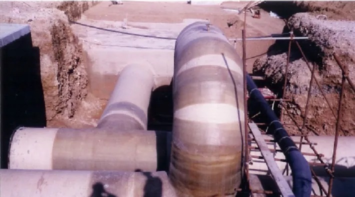
- Ready mix concrete with approved design & trial mix of 40N/mm2 and 20N/mm2.
- Reinforcement Steel Bars, Assorted sizes
- 18mm thick Phenolic Board (Plywood)
- Assorted Wood
- Cover & Frame
- Assorted Nails and Concrete spacer
- Marker Tape
- Tie Rods and Steel Clamps
- Cup-Lock with Steel Decking and Infill System
- 10mm Course Aggregates(natural)
- Polyethylene sheets, Absorptive Mats and Water
- Poly Release WB Mould/Shutter Release Agent.
- Geotextile Filter Fabric
General Requirements for Drainage & Sewage Works
Shop drawing for each line will be prepared and approved by consulting engineer prior to start the actual work.
Upon formal receipt of construction approval from the Engineer, setting out for the sewer lines will be carried out by the Contractor’s Surveyor, which will be agreed with the Engineer’s Surveyor before proceeding with any permanent work.
Any obstruction observed during site inspection will be recorded and photographed and confirmed in writing for reference and records, work will proceed in the event the proposed sewer is unaffected by obstruction.
In the event of obstruction conflict of any kind, necessitating relocation outside the allocated sewer reserve, the necessary permission for such relocation will be acquired by the Engineer.
Prior to dewatering, necessary approval will be obtained from the concerned authorities prior to discharge in existing drainage system.
All operation will follow contractors Safety Manual, and when there are omissions, client’s safety manual will be followed.
Copies of approved QA/QC Forms will be used for all approval procedures.
Procedure for the Storage of Pipes
The Pipes & Fittings will be stored in a shaded area for G.R.P pipes with tarpaulins to protect from direct sunlight and in accordance with manufacturer’s recommendations.
It will be ensured that the pipes and fittings do not come into contact with sharp projections.
The pipes and fittings will be stored in a flat level area and raised above the ground on timber so that the lowest point of any pipe or fitting is not less than 150mm above the ground.
Pipes will be stacked in such a manner so that the height of the stacked pipes does not exceed 2 meters.
The Spigot and Socket pipes will be stacked in such a manner so as to ensure that pipe layer have sockets protruding at opposite ends of the stack.
Rubber Joint Rings will be stored in an air-conditioned store.
Only nylon slings shall be used for lifting pipes and units (Transportation / Installation)
Segregation of damaged products (if any) is brought to the notice of Engineer for either repair or rejection of that pieces.
Dewatering
Where formation levels are below the ground water table, dewatering of excavations to be done utilizing well point dewatering system.
Pre-drill the wells using drill head fitted to the boom of a wheeled or chain excavator.
Well-points of 6 m. in length will be installed into the pre-drilled holes using jetting pumps.
The slotted filter heads of the well-points will be surrounded with sharp filter sand while jetting.
50 mm diameter UPVC well-points will be connected to 150 mm dia. Header pipes via 50 mm dia. Flexible hoses.
The header pipes will be linked to 150 mm diameter vacuum pumps which will pump the groundwater via 150 mm dia. Lay flat discharge lines, connected to 10” discharge lines laid up to approved discharge points. (Through a setting tank) to avoid sand going to the existing system.
Where Rock Is Encountered
A well point dewatering system will be installed approximately for the first 30 meter length, in order to establish a sump, from where the ground water will be slumped out by means of a suitable submersible pump or vacuum pump, if the formation area encountered by hard soil.
The available bore hole results will have due significance while deciding upon the method of dewatering for a particular area.
NOTES ON EXCAVATION
The Existing ground level will be recorded.
Excavation will proceed after successful dewatering wherever required.
Where sewer lines are located in areas unaffected by space restriction and are in areas of stable ground conditions, an open–cut excavation to the safe angle of repose of the soil will be adopted.
The deep excavation will be in stages as per depth band.
Where the proposed deep lines are located near an existing service or structure, use trench shoring box support for excavation prior to commencement of any such excavation.
Due care will be taken to maintain and support all the existing services and structures.
A night watchman will maintain a vigilance on the excavation and dewatering installations, to keep the excavation free of water or loose materials at all times.
Diversions will be carried out by safety barriers.
Access ladders or scaffolding staircase will be provided for ease of entry and exit from the excavations every 25 meter.
Inspection requests, will be given to the Engineer/Inspectors, for obtaining approvals at various stages in accordance with RFIA.
Available borehole results have due sign face upon the method of excavation and dewatering for a particular area.
The excavated material will be moved to a safe distance from the trench sides.
Adequate shoring, battering of excavation sides will be undertaken to ensure the trench remains stable & safe working environment.
Soft spots observed on excavation formation level will be notified to Engineer and replaced with suitable material as directed by the engineer.
PROCEDURE FOR CONSTRUCTION OF GRAVITY SEWER LINES PIPE LAYING
Approved drawing shall be reviewed by the Project Engineer & communicated to foreman in charge of pipe laying.
GRP pipes are to be laid in accordance with the manufacturer’s instructions concerning the laying of pipes and bedding for the same, as submitted for approval.
Written inspection requests will be given to the Engineer/Inspectors for approval of various stages of work, such as:
- Setting out
- Excavation & formation
- Side and above bedding
- Pipe Laying (Alignment & Levels)
- Water Test
- Deflection Test (Ball test)
- Backfilling
Upon receipt of the Engineer’s approval of the compacted formation, the bedding material will be carefully placed in the trench on the spread geotextile.
10mm Granular bedding material will be spread and levelled to the pipe gradient to a level of 2cm above the invert level, so as to have a compacted invert level.
The stacked pipes will be lowered carefully in to the trench and laid downstream to upstream.
Pipes will be laid in granular bed and surrounded by 10mm single size crushed aggregate, contained within approved geotextile trench lining material.
The pipes will be checked for line and level jointly by Surveyor and the Engineer’s inspector.
Each pipe joint will be enclosed with approved PVC wrapping tape.
Side bedding will be placed carefully by means of a crane and side discharge skip, discharging the materials centrally.
The side bedding will be compacted in 150mm layers, by using two hand compactors, simultaneously on either side of the pipe to impart symmetrical compaction.
Care must be taken that the compactor will not in any means have a direct contact with pipes to avoid damages.
Following this, the pipe surround material will be placed carefully in the same manner, to a level of 30cm in two layers above the crown of the pipe and compacted.
The Geo-textile Fabric overlap will be 30cm.
Selected materials previously excavated from the trench will be utilized to backfill the trench in 250mm layers, carefully compacted by hand rammers , up to level of 600mm above the crown of the pipe.
Water test in accordance with specification will be carried out as per the approved method statement.
When pipe laying is not in progress, ensure that the pipe ends are closed at all times by water-tight plugs.
Subsequently, backfilling will continue in layers, compacted in the lower regions by mechanical plate compactors and in the upper region by hand operated drum rollers and where the trench is wider than 2 meter vibrating steel roller shall be used.
Upon completion of the backfilling the 1st deflection test will be carried out (allowable limit: 3%)
A 2nd deflection test will be carried out immediately prior to PAC (allowable limit: 5%)
Compaction test will be carried out for the backfilling, as directed by the Engineer in unmade areas to a minimum Proctor density of 90%.
In areas under roads, the backfilling and compaction test will be carried out in accordance with specifications for backfilling of Trenches and Excavation in Tiled/Paved Parking’s and Roads.
A final mirror test is carried out to ascertain the alignment.
A 150mm wide service warning tape will be placed 800mm below FGL.
Procedure for Water Test for GRP Pipes
Complete the granular bedding up to the soffit of the pipe line
Fix stoppers end plugs both at the upstream and downstream with two pipes ½” dia. the upstream will be “air release pipe’, while the downstream one will act as ‘filling pipe’
Fill the line from downstream pipe (Filling pipe)
Keep the Air Release Pipe open to release the air.
When water starts coming from the Air Release Pipe, the pipe will be closed.
A pump will be fixed at the downstream end, fitted with a gauge and pressure applied equivalent to 5m of water head or depth to invert plus 1 meter whichever is greater.
Measure the head at the down stream end.
The pressure will be maintained for a period of 30 minutes.
If there is any drop in pressure, water will be added from a measuring vessel at 10 minutes intervals.
A record will be kept of the quantity of water added.
The added quantity of water should not exceed 1 liter per day per millimeter of nominal internal diameter, per kilometer of pipe.
Pipe line will be tested in length between manholes to manhole.
Procedure for backfilling
Trench backfilling will start immediately after the pipeline is tested and approved.
Backfilling will be carried out in accordance with the project specifications.
Approved backfill material will be utilized to backfill the trench in 250mm layers, carefully compacted by hand rammers up to a level of 600 mm above the crown of the pipe.
Subsequently, backfilling will continue in layers of 25cm compacted in the lower regions by mechanical plate compactors and in the upper region by hand operated drum rollers.
Compaction test will be carried out for the backfilling, to a minimum Proctor density of 90% under non-paved areas and 95% under roads and paved areas.
In areas under roads backfilling compaction tests will be carried out in accordance with the specifications for backfilling of trenches and excavation in tiles/paved parking and roads.
The frequency of tests will be in accordance with the requirements of the project specification.
Procedure for concrete bed & surround for GRP pipes
All procedures method will be the same as above except for the following:
100mm thick Class ‘C’ blinding concrete with hooks embedded to hold the pipes in position and level.
Concrete blocks for adjustment of pipe level placed at 3 meter intervals.
Concrete 20N/mm2 pipe surround with flexible joint at pipe joints.
Flexible sheet be provided at every joints.
Procedure for Construction of Chambers
Construction of these units shall be carried out in the following sequences and details, and it shall be understood throughout this method statement that every activity will be inspected and approved by the engineer prior to the commencement of subsequent activity.
Shop Drawing:
Proposed Location for Chambers will be surveyed based on approved drawings.
Preliminary setting out will be carried to assess the feasibility of filing the chambers.
Dewatering: Depending on the location of chamber and ground water presence, dewatering is required, shall be carried out as per method statement.
Setting Out: Setting out of manhole shall be done as per the approved shop drawings, excavation will be carried out along with the pipeline trenches.
Blinding: After obtaining the approval from Engineer for the formation level blinding concrete shall be laid to a minimum of 100mm thick.
Base: Shutter will either be steel or wooden shutter (Marine Plywood).
Sufficient cement cover blocks shall be placed to maintain a 75mm clear concrete cover at the bottom of base in case of reinforced chambers.
The Engineer shall inspect all formworks, reinforcement and water bar in wall kicker before placing the concrete.
Approved concrete of 40N/mm2 shall be placed in accordance with the contract requirements and it shall be well compacted with vibrators.
Care will be taken not to entrap air underneath the benching/liners.
Shuttering will be removed after concrete has gained sufficient strength to carry its own weight and imposed loads.
Curing of concrete will start after initial setting of concrete.
Wall: Construction of wall is done to the entire height of the wall in a single pour.
Internal & external shutter work will be carried out and proper support will be given to the shutter to avoid any deformation.
The concrete cover slab will be constructed separately with respect to road levels.
Procedure for pouring concrete, de-shuttering and curing shall be the same as described in base section above.
Protection of external concrete surfaces
External surfaces for concrete structures shall be protected with approved waterproofing membrane system as per specification and method statement of waterproofing.
Backfilling: Backfilling shall be done after the approval of waterproofing works and it shall be as per specification and method statement for backfilling.
Fixing the Cover & Frame: Frame and cover fixing shall be as per specification and method statement for fixing DI Cover and Frame.
Internal finishing for drainage chambers will be with 7mm of GRP in-situ lamination in three layers.
Upper face of the benching will receive a non-slip finish of silica sand.
Procedure for construction of manholes
1500mm Manhole on 150, 200 and 300 G.R.P dia. Sewerage Lines up to 6m Depth
Use a Pre-Fabricated 7mm thick one piece molding formed precisely to suit the required shape from approved GRP supplier manholes units as per standard details.
Prior approval of the manhole production schedule will be obtained.
Safety procedures will be adopted as described in the safety manual submitted and will generally comply with the requirements of project safety manual.
All manholes shall have a circular base unit above which a circular shaft shall be constructed. The base will be cast in a single part.
BASE: Upon receipt of the Engineer’s approval for the formation, concrete blinding to a thickness of 100mm will be poured and trowel finished to a top level 45cm below the top of benching of the manhole.
Base unit is fixed on line & level followed by shuttering benching is adequately loaded with sand bags to avoid uplift during casting.
Approved concrete shall be placed in accordance with contract requirement.
Wall & Cover Slab: Wall construction is done to the entire height along with cover slab, with preformed double skin liners used, from approved GRP supplier.
These double skin liners are used as concrete shutter during casting (with additional ring supports)
Lamination: (Internal & External) shaft joints are laminated by qualified laminator.
200mm thick concrete 40N/mm2; cover slab with 600 Dia circular opening will be as shown on plan Contract Drawing.
DI Cover & Frame (Class D400/B125) as specified will be fixed to line & level as per road camber on class C40 concrete.
Procedure for backdrop construction
The backdrop lower connection to manhole shall be fixed and cast along with the manhole base.
While casting manhole shaft, a plywood box frame shall be fixed at the backdrop upper connection level.
Backdrop construction shall start after finishing shaft construction; as per the following steps:
- An opening in the shaft GRP liner, with a size as per backdrop pipe size shall be prepared at the backdrop higher connection point.
- The backdrop pipe shall be fixed and connected, by lamination.
- Due to practicality, back drop concrete is done after shaft.
- Shutter shall be fixed around the pipe as per the required size and concrete will be poured.
Material approved for backdrop construction
UPVC pipes and fittings (1 Elbow and 1 Tee required) used shall be from approved supplier.
In some cases GRP Tee and Elbow may be required which will be obtained from approved supplier
Concrete shall be from approved batching plant
Lamination material from GRP Factory.
Procedure for reinforcement works
Reinforcing bars to be used shall be from approved Manufacturers/Suppliers.
IFC drawings for structures (steel reinforcement) shall be used for construction typical.
After obtaining the approval, the steel reinforcement will be cut to the required length and then bent to the required shape as per approved bar bending schedule.
The reinforcement steel shall be fixed as per the latest approved shop drawing.
Machineries and tools required for reinforcement works
- Mobile Crane
- Cutting Machine
- Bending Machine
- Pincers
- Protective Instruments: Hand Gloves, Eye Glasses, Helmets
- Steel Brush
Procedure for waterproofing works
Waterproofing material to be used shall be as per approved material submittal.
Approved material for water proofing works
Concrete – Primer (from approved membrane source)
Waterproofing membrane from approved source.
Tools required for water proofing works
- Gas torch (for membrane)
- Gas cylinder with regulator and associated hose pipe (for membrane)
- Trowel with round tip (for membrane)
- Measuring tape (for membrane & protection board)
- Rooter’s knife (for membrane)
- Protective safety tools, i.e. hand gloves, helmets, shoes
- Paint roller & paint brush (for primer)
- Plastic Bucket (for primer & plastic screed)
- Ladder
- Saw (for protection board)
- Hand shovel (for protective screed)
After the required curing time for the structure finishes, concreter surface shall be cleaned from any dust, oil or any other material that will prevent the adhesion between concrete and the base waterproofing material.
All external corners are to be chamfered and angle fillets formed with sand cement mixture are provided to all internal corners to prevent a 90º bend to the water proofing membrane.
A single coat of primer shall be applied as per manufacturer’s recommendation.
The primer is to applied evenly on the subsurface using a roller or brush. The primer shall be allowed to dry until ‘tack-free’.
Consultant shall check the application of primer prior to proceed with the installation of the waterproofing membrane.
After the approval is obtained, one layer of waterproofing membrane shall be applied to the ‘tack-free’ primed concrete surface; all membrane corners, overlaps and angles shall fully torched.
Any void or air gap must be corrected if found, by cutting, opening, patching with 150mm overlaps each side of cut.
The membrane shall be fully bonded to the subgrade, by torching evenly forming 100mm side laps and 150mm end laps.
All side end laps shall be fully bonded by torching so that a bead of molten bitumen appears at the seam. This bead shall be smoothened using a round trip trowel.
The consultant shall check the waterproofing membrane and shall be approved prior to proceed with the membrane protection system.
After the approval is obtained, protection sheet shall be fixed on vertical sides.
Overlapping between protection sheets shall be 150mm as per specification.
RFIA will be raised for Consultant′s approval.
Procedure for fixing DI Cover & Frame
Before fixing the DI Frame, surface of cover slab shall be chipped and cleaned; water proofing membrane shall be properly terminated on top edge of slab.
Also covers and frames must be coated before fixing.
Tools required for fixing DI cover and frames
- Hilti Drill / Mixer / Breaker
- Steel Trowel
- Plastic Bucket
- Protective Instruments; Hand Gloves, Eye Glasses, Helmet
- Mason Hammer
- Chisel
DI frame shall be installed as per the required level on cement blocks at the corners, which is 10cm by 10cm in width and depth respectively, while length shall be determined as per site requirements.
GRP liner edge shall be flush with internal face of the frame.
Plywood shutter shall be fixed inside at the internal face of the frame.
Proper external shutter as per the required dia. and height shall be fixed at the external side of the frame, with proper chamfering.
Concrete is to be poured to surround the DI Frame at the top of the cover slab.
The top surface of concrete shall be smoothly finished.
Curing shall be made to the period required by specifications.
Plywood shutter which was fixed inside the frame shall be removed and the inner face shall be prepared for lamination of a minimum of 7mm.
The outer face of concrete shall be painted with two coats of the approved bituminous paint.
GRP ceiling plate shall be fixed with EPDM rubber gasket and DI cover shall be fixed.
Procedure for GRP manhole liners
Site joint lamination shall be done as per approved subcontractor method statement and as detailed below:
Material required for site GRP lamination
- Surface tissue ‘C’ glass
- 300gm CSM ECR glass
- 450gm CSM ECR glass
- Pre-accelerated Vinyl ester Resin
- Isophthalic Resin
- Catalyst
- Flow Coat
- Filler Paste (if necessary)
- Acetone
- Empty Plastic Bucket
- Steel Roller 4” in length for Releasing the Trapped air
- 3” Wide Brush for cleaning the surface with Acetone
- 4” Paint roller for applying the Resin
- Metal pot to carry the Acetone on site.
Pre-accelerated resin, catalyst flow coat and filler pasted should be stored at a temperature below 20 Cº
Surface tissue and CSM should be kept at a non humid place. The Pre-accelerated resin has only one month shelf life.
All Surface to be joined should be clean dry and well abraded by grinder with 36 or 50 grade Sand Disc and a flexible backing pad should be used, all the resin rich surfaces should be grinded to expose the fiber so that the first layer of the in-situ lamination to be glass to glass. The minimum width should be 100mm.
The humidity level should be considered and it should be below 75% when the site lamination is carried out.
Prepare the 450g/m2 E glass (Advantix) CSM and ‘C’ glass veil surface tissue in minimum of 100mm wide strips.
The number of layers required for different lamination location is shown on the approved sketch (7 layers).
Mix Catalyst (1 to 2% by weight) to the pre-accelerated resins (Vinyl ester and Isophthalic specified in the sketch) in a bowl.
Catalyst should be measured using a Catalyst dispenser.
The percentage of Catalyst shall vary, according to the temperature the percentage of Catalyst should be less.
Bowl used should be clean and dry.
Apply a cost of Isophthalic (Vinyl ester) resin to the abraded surface with roller or brush.
Position the first layer of 450g/m2 C.S.M. directly on top of the resin and apply another coat of resin.
Consolidate the CSM by rolling with 2inch to 4inch metal roller to expel all entrapped air in it.
Continue this procedure until all the required layers of CSM (450) are positioned in place.
Position the layer of ‘C’ glass veil surface tissue over the final layer of CSM with Vinyl ester Resin and roll out all entrapped air until a resin rich surface is obtained.
The liner layer shall comprise one layer of glass surface veil 450gm/m2 and two layers of CSM 300gm/m2, ‘Advantex’ powder bounded corrosion resistance or any other equivalent approved type, impregnated with Vinyl ester resin of approved type with a glass resin ratio of 25:75 and a tolerance of +/- 5%.
The structural layer shall comprise of six layer of chopped strand mat 450gm/m2 ‘Advantex’ powder bounded corrosion resistance or equivalent approved type, impregnated with Isophthalic resin of approved type and 0.5mm flow coat on the external surface with resin of approved type with a minimum glass resin ratio of 70:30
Wash all the tools (metal rollers, brush, etc.) with acetone before the resin sets.
Wait until it is cured.
Apply a Vinyl ester flow coat with paraffin wax and after it is cured, all shall be cleaned and puffered properly.
Attachments
- Inspection Checklists
- Inspection Test Plan
- Risk Assessment
- Technical Data sheet (TDS)
- Approved Drawings / Sketches
Discover more from Project Management 123
Subscribe to get the latest posts sent to your email.