For the design of bridges foundation, the scope of subsurface exploration shall be to determine soil parameters and rock characteristics and their suitability by insitu testing or testing of samples/cores taken out of exploration.
It shall be planned in such a way that the profiles of different types of soil and/or rock up to the desired depth for at least in the full length of the proposed structure are recorded and other information such as physical/mechanical properties like grain size distribution, sensitivity, existence of deleterious materials, etc. in soil and/or ground water etc. are also determined.
Field Investigation Phases
Unless otherwise specified, the field investigation of subsurface shall be carried out in three phases, namely, Reconnaissance, Preliminary Explorations and Detailed Explorations.
Reconnaissance
It shall include review of available topographic and geological information, aerial photographs and data from previous investigations and site examination.
Preliminary Explorations
It shall include the study of existing geological information, previous site reports, geological maps/aerial photos interpretations, and sub-surface geological examination.
Geophysical investigations of the site shall also be conducted during this phase in order to have information about stratifications.
Detail subsoil exploration shall be planned depending on these information.
Preliminary exploration shall be carried out to determine the soil profile showing the boundaries between the different types of soil and between loose and dense parts in the same type of deposits.
For this purpose, as a first step, a suitable type of sub-surface sounding (e.g. static or dynamic cone penetration test) shall be carried out.
As many soundings as necessary shall be made until penetration data is complete to provide the general shape and the trend of boundaries of the various soil deposits.
Exploratory drill holes shall then be made at one or two locations where average condition prevails and near those points where the penetration diagrams indicate maximum deviations from the average.
Detailed Explorations
The scope of the detailed exploration shall include boring program based on data obtained after preliminary investigations.
The bridge site, types of structure with span arrangement and the location & type of foundation shall be tentatively decided based on data obtained after preliminary investigations.
Extent of explorations, number of boreholes, type of soundings, types and number of tests, open trial pits, etc., shall be decided for the execution of the exploration so as to collect adequate data considered necessary for the detailed design and execution of the related structure.
For bridge works, the investigations shall be comprehensive enough to enable the designer to estimate or determine the followings:
(a) the engineering properties of the soil and/or rock,
(b) the location and extent of soft layers under the hard founding strata,
(c) the geological condition like type of rock, faults, fissures or subsidence due to mining, porosity etc.,
(d) the ground water level,
(e) artesian conditions, if any,
(f) the location, type and extent of different layers,
(g) quality of water in contact with the foundation,
(h) probable settlement and probable differential settlement of the foundations,
(i) likely sinking or driving effort,
(j) likely construction difficulties,
(k) the depth and extent of scour,
(l) suitable depth of foundation, and
(m) bearing capacity of the foundation.
Methods of Geotechnical Exploration
Any of the following methods of exploration or their combination shall be used depending upon type of structure and strata.
- Geophysical Exploration
- Test/Trial Pits
- Boring
- Static Cone Penetration Test
- Dynamic Cone Penetration Test
- Plate Load Test
- In-situ Vane Shear Test
Geophysical Exploration
Use of geophysical methods shall be limited to the detection of voids, buried channels or rock mass classification.
The two main geophysical methods to be used shall be:
(a) Electrical Resistivity Method.
(b) Seismic Method.
Test/Trial Pits
Test/trial pits shall be used for direct visual examination of the soil and its stratification including water table.
This will also allow for the execution of in-situ tests like plate bearing tests, shear tests, etc.
A test/trial pit shall be at least 1 m square at the bottom of the pit.
The depth of the pit shall be 3 m, unless otherwise specified. Below a depth of about 1.5 m, the sides of the pit shall be supported or shall be excavated at safe angle.
Pits shall be left open for some time so that seepage lines on the sides of the pit can be examined and the existing ground water level can be indicated.
Borings
Boring a hole shall be started by driving casing to prevent it from caving in.
Casing shall be cleaned by means of chopping bit, etc., with the water pumped through drill rod and water overflows at the top carrying soil particles.
The hole shall be advanced by raising, rotating and dropping the bit into the soil at the bottom of the hole.
In rotary boring, drill bit shall be rotated with the simultaneously application of pressure to advance the hole.
In case where sample disturbance is not critical, hand or powered auger boring can also be carried out with the prior approval of the Engineer.
General Requirements of Boring/Drilling
The equipment for boring shall be automatic hydraulic or mechanical feed with properly working indicator of drilling pressure.
The equipment shall be with transmission gear to adjust spindle speed.
The Contractor shall supply all necessary flush water for the execution of boring and pertinent tests. Clear water shall only be used.
Nevertheless, the equipment shall be capable of handling mud flush.
The barrels for boring shall be double tube core barrel. Only in certain circumstances, use of single tube core barrel shall be allowed.
The drilling machine shall be equipped with different sizes of casings in order to allow proper telescoping of definite sizes.
The final diameter of the borehole shall be such that allows extraction of samples with proper dimension in order to properly conduct tests, such as consolidation, shear, triaxial, permeability, etc.
Methods of Boring
Boring shall be done by any of the methods mentioned below depending on the soil type and types of samples required for the investigation.
The two main geophysical methods to be used shall be:
(a) Electrical Resistivity Method.
(b) Seismic Method.
Test/Trial Pits
Test/trial pits shall be used for direct visual examination of the soil and its stratification including water table.
This will also allow for the execution of in-situ tests like plate bearing tests, shear tests, etc. A test/trial pit shall be at least 1 m square at the bottom of the pit.
The depth of the pit shall be 3 m, unless otherwise specified.
Below a depth of about 1.5 m, the sides of the pit shall be supported or shall be excavated at safe angle.
Pits shall be left open for some time so 1I1at seepage lines on the sides of the pit can be examined and the existing ground water level can be indicated.
Borings
Boring a hole shall be started by driving casing to prevent it from caving in.
Casing shall be cleaned by means of chopping bit, etc., with the water pumped through drill rod and water overflows at the top carrying soil particles.
The hole shall be advanced by raising, rotating and dropping the bit into the soil at the bottom of the hole.
In rotary boring, drill bit shall be rotated with the simultaneously application of pressure to advance the hole.
In case where sample disturbance is not critical, hand or powered auger boring can also be carried out with the prior approval of the Engineer.
General Requirements of Boring/Drilling
The equipment for boring shall be automatic hydraulic or mechanical feed with properly working indicator of drilling pressure.
The equipment shall be with transmission gear to adjust spindle speed.
The Contractor shall supply all necessary flush water for the execution of boring and pertinent tests. Clear water shall only be used.
Nevertheless, the equipment shall be capable of handling mud flush.
The barrels for boring shall be double tube core barrel. Only in certain circumstances, use of single tube core barrel shall be allowed.
The drilling machine shall be equipped with different sizes of casings in order to allow proper telescoping of definite sizes.
The final diameter of the borehole shall be such that allows extraction of samples with proper dimension in order to properly conduct tests, such as consolidation, shear, triaxial, permeability, etc.
Methods of Boring
Boring shall be done by any of the methods mentioned below depending on the soil type and types of samples required for the investigation.
(a) Auger Boring (Manual and Mechanical)
(b) Percussion Boring
(c) Wash Boring
(d) Rotary Boring
(a) Auger Boring
(i) Hand Auger Boring
In the hand auger boring method, light hand operated equipment shall be used.
The auger and drill rods shall be lifted out of the borehole without the aid of a tripod and no borehole casing shall be used. Boreholes up to 200 mm diameter shall be made in a suitable ground condition up to a depth of about 5.0 m.
Hand auger boreholes shall be used for ground water observations and to obtain disturbed samples and small tube samples.
Mechanical Auger Boring
Small portable power augers, shall be suitable for boring to depth of 10- 15 m. The hole diameter shall be in the range of 75 to 300 mm.
Percussion Boring
Adaptation of standard boring methods shall be suitable for soil and weak rock.
The size of the borehole casing and tools shall generally be 100 mm, 150 mm, 250 mm and 300 mm giving a maximum borehole depth of about 60 m in suitable strata.
The drill tools, hooked on a wire rope using the clutch of the winch for the percussion action, shall be a clay cutter for dry cohesive soils, a shell or baler for cohesion less soils and a chisel for breaking up rock and other hard layers.
The clay cutter and shell shall bring up disturbed material for laboratory testing and identification of strata.
Wash Boring
Wash boring shall be carried out as per IS ,BS , ASTM or equivalent standard.
Rotary Drilling
In rocky strata rotary drill shall be used. Open hole drilling, in which the drill bit cuts all the material within the borehole, shall be used for more rapid progress in hard material.
Better quality samples of soil and rocks shall be obtained using core drilling, in which an annular bit fixed to the bottom of outer rotating tube of a rotary core barrel cuts a core, which is retained within the inner stationary tube of the core barrel and brought to the surface for examination and testing.
Size of the Borehole for Sampling
Rotary drills and/or percussion drilling shall be used for getting undisturbed soil sample.
The size of casing shall be sufficient to provide space for retrieving undisturbed sample by sampler tube for soil.
For rock sample, the size of casing shall be sufficient enough to allow use of single or double tube barrel as required for retrieving core sample.
Condition of Boring
While conducting detailed borings, the resistance to the speed of drilling i.e. rate of penetration, core loss, etc., shall be carefully recorded to evaluate the different types of strata and to distinguish specially sand from sandstone, clay from shale, etc.
For good coring either in soil or in rock, the driller shall carefully watch and record the speed of the rate of cutting of bit, bit pressure, bit feed, pump pressure and discharge.
Extent of Boring
The depth of boring shall depend upon the type of proposed structure, its total weight, and type of subsoil encountered. Normally tests shall be taken down below the foundation level depending upon the type of
foundation e.g.
(a) foundation requiring shallow depth: up to a depth: where the magnitude of stress due to the structure load is equal to 10% of the overburden pressure, but at least one boring shall be made deep enough preferably up to hard strata
or rock to ascertain the existence of any exceptionally compressible stratum that are unsuitable for foundation
(b) for rock foundation: until sound bed rock is reached and confirmed by at least 3 m coring by rotary drilling. In sound bed rock more than 6m drilling may not be required. In residual profile it may be necessary to drill further 3 m to differentiate rock from drill bit the boulder.
The spacing of borings shall be such as to reveal any major changes in the thickness, or properties of the strata over the base area of the structure and in its immediate vicinity.
A preliminary estimate of spacing may be modified depending upon the information revealed by boring.
The Boring Agency shall notify the Engineer the situation and shall seek his approval for such modification(s).
Records of Test/Trial Pits and Borings
For all test/trial pits and borings, general information as detailed below shall be given.
A site plan showing the position of the bore holes/trial pits shall also be attached.
(i) Boring Company
(ii) Location with reference map
(iii) Pit /Bore -hole number
(iv) Reduced level (R.L.) of ground surface or other reference point with arbitrary permanent Bench Marks
(v) Dates of starting and completion
(vi) Name of supervising engineer and driller
(vii) Dimensions and methods of advancing exploration
(viii) Any other information and remark including weather/climatic condition, difficulties encountered, etc.
Bore Hole Log
The final bore hole tog shall be based on the visual examination, description of the samples, laboratory test results, driller’s daily report forms and geology of the site. All the relevant data collected by the driller, once checked and amended where necessary, shall be recorded.
The bore hole log shall be maintained in the format shown in below table.
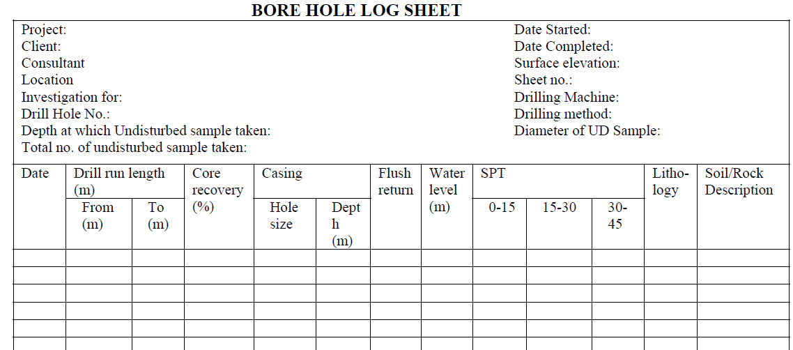
The bore log shall contain the elevation at which the water table and the upper boundary of each of the successive soil strata were encountered, the investigator’s classification of the layer on the basis of general information obtained from field examination and the value of the resistance obtained by means of Standard Penetration Test (hammer wt.65 kg & falling height 75 cm for rotary drilling attached with standard split barrel sampler at the bottom connected with drill
rod) or Static Cone Penetration as specified.
The type of tools used for boring shall be recorded. If the tools were changed, the depth at which the change was made and the reason thereof shall also be noted.
Incomplete and abandoned borings shall be described with no less care than successfully completed drill holes.
The notes shall contain everything of significance observed on the job, such as the elevation at which wash water was lost from the hole, etc. All field and final logs shall be signed by the supervising Engineer.
Sample Core Recovery and Core Boxes
Only samples that are unaltered and not damaged by drilling process shall be considered as core.
Core drill shall be so designed that in sound rock, continuous recovery is achieved.
Run shall be short in order to achieve maximum core recovery.
Where there is core loss, it shall be noted on field borelog.
It shall be shown by placing wooden stick in the core box so that Engineer can judge how much core has been achieved.
For getting disturbed soil (granular) sometime water is circulated down the hollow rods which returns outside them, carrying the rock cutting to the surface as sludge.
These shall be retained as samples in transversing friable rock where cores cannot be recovered.
It shall be ensured that boulders or layers of cemented soils are not mistaken for bedrock. For laboratory determination of uniaxial compressive strength of rock materials, the final size or dimensions (minimum) of the specimen shall be after trimming in the form of circular cylinder having height to diameter ratio of 2.5 to 3.0 and the diameter of core shall not be less than 54.7 mm.
Sufficient quantity of core boxes shall be available at site before the commencement of boring. Further drilling works shall be stopped if it is found that boring is carried out without core boxes and undisturbed sampler tube.
The core box shall be made of good and durable material.
The boxes shall bear lids and hinges. The files inside the core boxes shall have a length of 1.05 m.
Cores shall be placed in core boxes in a proper order and direction.
The end of each core run shall be marked by a cross piece with indication of depth. The box shall provide information on borehole, depth of corresponding core, number of box etc.
The coreboxes shall be transported to the location instructed by the Engineer.
The provided core with coreboxes shall be available for inspection as and when required by the Engineer.
The boxes shall be the property of client.
The cores shall be carefully extracted out of the core barrel and placed in core boxes. Core shall correspond each time to the fixed depth with accuracy of 1 cm.
A minimum core recovery of 80 % in hard rock and 50 % in other strata (except sand strata) shall be achieved.
If possible none or minimum quantity of water shall be added while boring through soft cohesive soils and cohesionless soils above water table in order to maintain its natural moisture content and stress condition for further
in-situ and laboratory tests.
Sampling
There shall be two types of samples,
(a) Disturbed sample and
(b) Undisturbed sample.
Disturbed Sample for Soil
Types of disturbed samples shall be:
- Hand Samples
- Auger Samples
- Sludge Samples
- SPT Sample
- Sample Extracted from Barrel
Disturbed samples shall be obtained in the course of excavation and boring. For taking samples from below the ground water level, special type of sampler shall be used.
Where standard penetration test is conducted, representative samples shall be obtained from the split spoon.
Quantity of samples required for laboratory testing shall not be less than as shown in below table.
Disturbed Sample for Rock
The sludge from percussion borings or rotary borings which have failed to yield a core, shall be collected as disturbed samples.
It may be recovered from circulating water by settlement in a trough.
The types of disturbed samples shall be:
- Wash Samples from Drilling
- Sludge Samples
Undisturbed Sample for Soil
Samples shall be obtained in such a manner that moisture content and structure do not get altered. This shall be ensured by careful use of correctly designed sampler, protection and packing.
Type of undisturbed sampling sampler shall be as follows:
A. Block sampling (Hand Samples) shall be carried out by manual excavation inside the trench or pit.
B. Thin-walled Sampler Tube: for soft and firm soils (internal diameter 75mm to 250 mm)
C. Open Tube Sampler: for firm to stiff clays, disturbed samples for weak rock (100mm diameter open tube sampler,
like U100)
D. Stationary Piston Sampler: for soft sensitive clays, noncohesive fine grained soil and firm to stiff soils not containing coarse material.
E. Sand Sampler: for silts and sands below the water table (like Bishop sand sampler)
For compression test, samples of 40 mm diameter and 150 mm to 200 mm length may be sufficient, but for other laboratory tests, samples of 100 mm diameter and 300 mm length shall be taken unless otherwise instructed by the Engineer.
While preparing samples the upper few millimeters of sample shall be removed.
Undisturbed Sample for Rock
A. Block samples: Such samples taken from the rock formation shall be dressed to a size about 90x75x50 mm.
B. Core samples: Cores of rock shall be taken by means of rotary drills fitted with a coring bit with core retainer and
the diameter of core shall be as mentioned in relevant clauses.
Frequency of sampling shall be at every change in stratum and at intervals not exceeding 1.5 m within a continuous stratum.
| S. No. | Purpose of sample | Soil type | Wt. of sample (kg) |
| 1 | Identification, Natural moisture content, Mechanical analysis and index properties | Soil | 2 |
| 2 | Identification, Natural moisture content, Mechanical analysis and index properties | Sand | 5 |
| 3 | Identification, Natural moisture content, Mechanical analysis and index properties | Fine to medium type of gravel | 5 |
| 4 | Identification, Natural moisture content, Mechanical analysis and index properties | Coarse gravel | 30 |
In situ Testing for Boreholes
In course of boring works, in situ test as mentioned below shall be carried out for the determination of bearing capacity.
Other tests like permeability, etc. shall also be se of carried out as directed by the Engineer.
In particular, following tests shall be conducted:
(i) Standard Penetration Test (SPT)
(ii) Vane Shear Test
(iii) Insitu Deformation Properties and Strength Measurements from a borehole using Pressuremeter.
(iv) Other tests as applicable.
Where undisturbed soil sampling, in-situ vane shear test and SPT are to be carried out in one layer, the sequence shall be undisturbed soil sampling followed by in situ vane shear test and SPT.
Protection, Handling and Labeling of Samples
Care shall be taken in handling, labeling and transportation of samples so that they shall be received in an acceptable state for identification, examination and testing.
The disturbed material in the upper end of the tube shall be completely removed before applying wax for sealing.
The length and type of sample so removed shall be recorded.
The soil at the lower end of the tube shall be reamed to a distance of about 20 mm.
After cleaning, both ends shall be sealed with wax applied in a way that shall prevent wax from entering the sample.
Wax used for sealing shall not be heated to more than a few degrees above its melting temperature.
The empty space in the samplers, if any, shall be filled with moist soil, saw dust etc., and the ends shall be covered with tight fitting caps.
Static Cone Penetration Test
This test shall be carried out for deep foundation of bridges for cohesive soil according to the stipulations of IS: 4968 (Part 3) or equivalent standard.
Dynamic Cone Penetration Test
This test shall be carried out as per IS: 2131. Wherever applicable, this test shall also be carried out as per IS: 4968 (Parts 1 &2).
Plate Load Test
For cohesion less soil in deep foundation, plate load test shall be carried out as per IS: 1888.
In-situ Vane Shear Test:
Vane shear test shall be conducted as per IS: 4434 on cohesive soil for deep foundation.
Exploration for Foundation Resting on Rock
The basic information to be obtained from the exploration shall be as follows:
(i) Depth of Rock strata and its variation over the site
(ii) Whether isolated boulder or massive rock formation,
(iii) Extent & character of weathered zone
(iv) Structure of rock- including bedding planes, faults, fissures, solution cavities etc.
(v) Properties of rock material strength, geological formation etc.
(vi) Erodibility of rock to the extent possible.
(vii) Colour of water/sludge
Exploration for Foundation Resting on Rock
The investigation shall be generally to that required for rock.
The samples collected shall be subjected to suitable tests depending upon the material.
Care shall be taken to ascertain erodibility of the matrix.
For shallow foundation, Plate Load Test shall be conducted.
Investigation for Laterites
The investigation shall be generally similar to that required for cohesive soils, use of penetration tests shall be preferred if suitable correlation charts are available.
This may be static or dynamic penetration tests or vane shear tests.
In the case of hard laterite, recourse may have to be made to core drilling as for soft rocks. For laterites at shallow depths, Plate Load Test shall be conducted.
Laboratory Testing for Geotechnical Investigation
Laboratory tests shall be carried out on disturbed, undisturbed samples and on rock extracted by pitting or boring as per requirements for the related type of structure.
Tests shall be carried out among the followings as per contract or as directed by the Engineer:
- Grain Size Analysis
- Hydrometer Analysis
- Bulk and Dry Density
- Specific gravity
- Natural Moisture Content
- Atterberg’s Limit Tests
- Unconfined Compression Test
- Consolidation Test
- Direct Shear Test
- Sulphates and Chloride test
- Vane Shear Test
- Point Load strength test on rock
- Uniaxial compressive strength Test
Triaxial Tests:
- Unconsolidated Undrained Test
- Consolidated Undrained Test
The above test shall be carried out as per Section 600 of these Standard Specifications.
Water Samples
If a trial pit has been excavated or a well exists near the site of exploration, water samples shall collected.
In the case if boring, it shall be collected from the borehole with the help of a common suction pump having a hose pipe, rubber tubing etc. which can be conveniently lowered down into the borehole connected at the suction end.
Minimum 5 liter of water sample shall be collected into a clean vessel and sent to the laboratory for chemical tests.
Tests shall be carried out in accordance with IS: 3025 or equivalent standard as per direction of the Engineer.
Discover more from Project Management 123
Subscribe to get the latest posts sent to your email.