This procedure defines the methods to be adopted for the installation of Busbar System. Document ensures that the electrical installation works at site are in compliance with the approved shop drawing and approved material submittal.
Scope of this method statement is procedure for Material Delivery Inspection, storage and Installation of Busbar system.
During the receiving of the materials, equipment shall be carefully off loaded at site using the necessary manpower, appropriate shifting machinery and equipment to ensure that no damage is caused to the material. All material shall be stored in a clean, dry place and adequate cover shall be provided to avoid damages.
Prior to commencement of work, areas and access will be inspected to confirm that site is safe and ready to commence the work.
Below is list of mandatory tools and equipment’s for the installation works.
- Electric drill hammer
- Torque wrench
- Electricians tool box
- Certified mobile scaffolds / step ladder
- Multi tester/ Megger tester
- Lifting Equipment/Chain block
Sequence of Busbar Installation Works
All relevant Documentation (drawings, material submittals, method statements etc.) and material applicable for particular area of work will be checked by site supervisor/engineer prior to the commencement of work.
The supervisor and foreman will examine surfaces to receive the bus bar for compliance with installation tolerances and other required conditions, as described in the manufacturer installation requirements.
Installation will not proceed until unsatisfactory conditions have been corrected.
The supervisor and foreman will orient and familiarize all the technicians and labors involved in the installations regarding the relevant approved shop drawings, technical submittals, installation procedures and details, acceptance criteria and safety requirements.
Bus Duct and Bus Bar Trunking Installation Package – Download Editable Files
Marking Busbar Routes / Support Locations & Shifting
Bus Bar riser routes to be marked on the slab / riser shaft prior to starting the installation. Mark the support locations in coordination with other services and to be installed as per approved shop drawings.
Check the level of the wall/slab with the use of spirit level and adjust the threaded rod length accordingly to maintain level of the installation as per approved drawings.
Minimum space from the building structure and other services to be maintained to facilitate easy handling, easy access to joints, maintenance of cables & protection.
Shift the busbar on Pellets to the installation locations using a fork lift of suitable capacity.
Installation of Busbar Flange on Panel board
Switchboard flanges are to be fixed on the top of the relevant Panel cubicle feeding the bus riser according to the location as shown in the approved shop drawing.
Supporting plate or top plate of the panel board cubicles are to be cut according to the fixing sizes as required the installation of panel board flanges.
While fixing the flange on the switchboard cubicle, the phase orientation of the switchboard flange should be according to the orientation shown in approved drawing.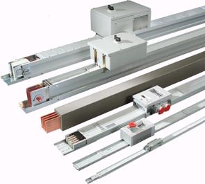
Ensure that no undue stress is transmitted to the top of MDB Panels during & after installation of Busbar.
Installation of horizontal run Busbar
Before placing each feeder element check the insulation value using a megger at 500V. If the insulation value is greater than 1000 ohm/V applied for each circuit, then the result is positive (i.e. 0.5 M ohm at 500V).
Fix the support as marked on slab. Make sure that slab support can take the weight of the bus bar. The support and fastener should carry 200 lbs. (90kg.) or 4 times the weight of the bus assembly.
Fix threaded rods of required length at the marked locations at distances as per approved installation details.
Length of the threaded rod from slab to be such that after fixing the clamp of suspension bracket, position of feeder element must be at the levels as indicated in the approved shop drawings.
Place the busbars in the suspension bracket matching the fixing holes between adjacent busbars.
During installation ensure that both ends of feeder elements are properly protected from any water splash, conductive liquids, dust cement & other harmful waste deposits. Make sure to cover up all unattended busbars ends properly.
Identification labels are to be fixed on busbar at regular intervals.
Busbars shall be covered with plastic sheets until the building is clean, ready to test & energize.
Offset to be used to avoid obstacles such as pipes, steel columns etc. and to conform to the structure of the building.
It is basically two elbows fabricated into a single piece for use where space prohibits the use of two standard elbows.
Four types of offset to be used (Flatwise Offset Up & Down, Offset left & Right).
Bus Duct and Bus Bar Trunking Installation Package – Download Editable Files
Installation of vertical run Bus ducts
Markings through the vertical riser wall to be checked by using plumb strings & spirit level. Proper level adjustment is to be done on the angular base on which the suspension bracket clamps are to be fixed (in case the building wall is not straight) so that busbar riser elements are fixed in an accurate straight vertical line from top to bottom.
Ensure that complete vertical route fixing area of busbar riser is clean and free from dripping water, dust and other waste deposits. Also make sure to prevent any chance of dropping water, dust and waste deposits during construction on bus riser until the complete installation is over with fixing of joint cover plate.
Ensure that the angle supports in the riser is fixed horizontal by means of spirit level and are inline to achieve the vertical route.
During installation do not load the expansion element with the weight of feeder element positioned above. Fix the clamp of vertical hanger as per the approved drawing.
Before fixing the first feeder element ensure the flat elbow at the beginning of vertical bus riser is fixed properly to the horizontal run. Place the feeder element to be fixed at the beginning of the vertical bus rise above the flat elbow at distance as shown in the approved drawing. Slide in the feeder element to the adjacent one until the earth duct lock is similar to the horizontal run joining. Repeat the same procedure.
Provide expansion joints after every 40 m of straight run or according to the manufacture’s recommendation, as well as on every building expansion joint.
Fire barriers shall be provided at floor penetrations in vertical runs and penetrations through fire rated walls for horizontal runs, as required for maintaining fire rating of surroundings areas.
Joining feeder elements
Before joining the elements make sure that the edges of feeder element and Joint pack connector are clean and completely free from dust and other waste deposits.
This precaution has to be taken care for all joints. After placing the adjacent feeder elements, the joint pack connector to be tightened using fixing bolts to manufacturer recommended torques to ensure the required contact pressure on the conductors and tie channels.
The fixing bolts at all joints to be tightened by using a torque wrench with manufacturer recommended torque settings.
Busbar Inspection and Testing Procedure
Ensure that all instruments and devices intended to use for testing must be calibrated. Attach all calibration certificates in the work inspection request showing the date and record of calibration.
Continuity test and insulation resistance test to be done for each and every section of the Busbar before and after installation (the mega ohm reading should not be less than the value recommended by the manufacturer). Check the busbar duct system properties such as tie channels, busbar, insulation, rating, length etc.
Ensure installation of Busbar assembly are carried out in accordance with manufacturer’s and local legal recommendations, requirement of applicable standards and in accordance with recognized industrial practices and specified project specification.
Check physical properties of busbar duct system if free from any damages, twisting or defects.
Prior to Energization, installation shall be checked and inspected by authorized representative from manufacturer.
Bus Duct and Bus Bar Trunking Installation Package – Download Editable Files
Discover more from Project Management 123
Subscribe to get the latest posts sent to your email.