
The purpose of this method statement is to implement the correct practices for installation of telephone system on a project.
By following the guide line contained herein the contractor shall ensure that the telephone system installation works comply with the project requirements and serves the intended function as per the client satisfaction.
Telephone system accessories shall be in line with the approved material submittals and approved drawings by local communication company as per applicable rules and standards.
TOOLS / EQUIPMENT
Below is list of necessary tools and equipment for the installation works.
- Micro test Scanner
- Label Printer
- Fiber Eye
- Drill Machine
- Fiber Tool Kit
- Ladders
- Wire Scope 155
- S110 punch down tool
- Power Meter
- RJ45 termination tool
- FOTEC OTDR
- Crimping tool
- Advantest
- Cable Toners
- FIS Tool Kit
- General tool Box
- FIS Fiber Tool Kit
- Fire Extinguisher
- Talk set
- Omnis Scanner
- Fujikawa
- DTX Analyzer 1800
- Blow Lamp
- Cleaver
- Krone Tool
- Portable hand tools
- Splice Machine
- Spirit Level / Level Threads
- OTDR
- Digital multimeter
MATERIAL HANDLING & STORAGE
On receipt of the Telephone System accessories at site, necessary precautions shall be taken for unloading, shifting & storage, as follows:-
All packages for the complete set of Telephone System, reaching to site shall be identified as per package list.
Where auxiliaries are shipped loose, these will be identified and checked against the dispatch documents.
Any item found missing or damaged will be notified to the supplier immediately for the replacement / repair.
Special attention shall be paid to the instruments and monitoring devices supplied loose.
All materials received at site shall be inspected to ensure that the materials are as per approved material submittal, shop drawing and single line diagram.
Any discrepancies, damage etc., found will be notified and reported for further action as per the standard procedure.
Site engineer will ensure that material used at site are free from any damage or deformity.
All packages shall be stored in a protected area.
INSTALLATION PROCEDURE
Telephone system shall be installed & tested by approved specialist supplier representative.
Ensure all civil works are complete for the area including floor paint to carryout the installation, and clearance is obtained from respective authorities to proceed further.
Prior to start the installation, refer to the approved shop drawings related to the area of installation and ensure that required materials are available at site as per approved material submittals.
Ensure the materials are stored properly and there is no mark of damage or deformity of any kind before issuing the material from site store.
INSTALLATION OF TELEPHONE CABLE
Installation of Telephone cables shall be taken – up through the containment system for Telephone points to junction box.
Proper care shall be taken while laying the cable to maintain the required safe distances from electrical equipment’s and power sources to avoid the main source of interfaces.
Ensure the cabling is done in proper way without any stress on the cable, while laying at the turnings, by keeping enough slack and proper bending radius.
Also make sure that enough slack is kept in the cable on both ends to allow the cable termination.
Telephone cables shall be identified on both ends as per method shown in approved shop drawings and as per local communication company’s requirements.
Continuity testing shall be carried out for each pair / loop of Telephone cable by using continuity test meter and result will be recorded for review and approval.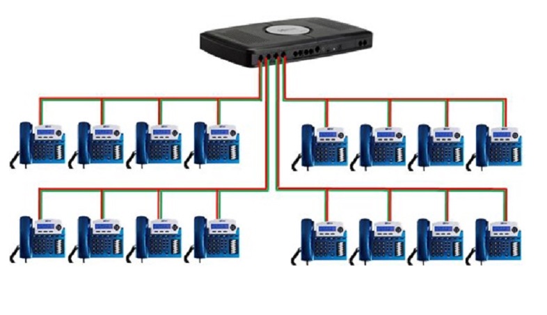
After completion of entire Telephone cabling and approval by consultant, cable termination shall be carried out in MDF and JB’s by contractor and in outlet by local telecom company.
The pair and locations feeding are identified in the Main Distribution Frame as per approved shop drawing.
MDF and JB’s will be identified with tags as per approvals.
All work shall be carried out according to local communication company’s requirements and as per their latest design guide for Telecom & Board band service requirements in new buildings.
INSTALLATION OF TELEPHONE SYSTEM EQUIPMENT
Main Distribution Frame will be installed in Telephone room as shown in detailed approved shop drawings.
Required rack ways shall be installed to interconnect back bone cable ducting to MDF and JB ‘s.
Installed MDF, JB’s & containment shall be checked for the proper locations and approved by consultant’s to proceed for the cabling works.
EARTHING OF TELEPHONE SYSTEM
An earth pit for clean earth will be provided out side main Telephone room.
Earth resistance of the earth pit will be measured and ensured that the value is with in permissible limit specified by local communication company.
Earth cable of size as mentioned in drawing & as required by local communication company will be laid from earth pit to Main Distribution Frame.
Proper termination shall be done at earth pit as well as MDF by using suitable terminal end connectors & as recommended by local communication company.
Metallic frame of MDF shall be earthed and other screens of cables shall also be bonded together and connected to earthing terminals.
Tightness of all connections and earthing continuity shall be checked.
Installation of Telephone System shall be inspected and approved by the consultant.
ATTACHMENTS
Risk Assessment
Inspection and test plan ITP
Quality control procedure
Inspection Check Sheets
Discover more from Project Management 123
Subscribe to get the latest posts sent to your email.