Below is best construction method statement that also covers the quality planning at construction site of civil engineering project.
Below is list of activities that are covered in this civil contractor method of statement.
Excavation work, including soil excavation, soil disposal, backfill and underground water disposal to ensure quality of foundation work.
Formwork, including all kind of formwork for structure concrete elements, form removal and rebar etc.
Concrete work, including all kinds of concrete elements casting, testing, curing and defect treatment.
Steel structure erection work, including assembling, connection and fabrication of steel members.
Excavation Works
Surface Preparation
Before the excavation, the surface shall be made free of all kind of materials.
Decide in advance the area to be used for temporary stockyard of excavated soil.
Layout of excavation area, by means of driven wooden post, dimensions with inclined open-cut angle included.
Excavation Steps
Excavation shall be made mainly by machine ( bulldozer, excavator and dump truck) with inclined open-cut angle of 60°.
Surplus excavated soil shall be disposed from site immediately daily.
At bottom of excavation, soil bed shall be leveled compacted until designed level by machine or manually.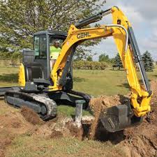
For excavation depth more than 1meter and incase underground water available, retaining wall shall be provided. The detail is as following. (refer relevant sketches)
Septic tank, water tank shall have proper planning of wall retaining (refer detail drawing for reference).
Bench mark shall be provided along building area in order to ensure correct excavation depth.
Water Disposal
Incase underground water is available, pump shall be arranged to drain it from excavated area before any further job.
Incase of rain, excavation shall be temporary stopped, the next excavation shall follow HSE requirements of the project.
Backfilling Material: The prior excavated soil shall be used for the backfill, provided that all organic remain shall be excluded.
Area cleaning: All kind of wasted materials remaining in backfill area shall be disposed completely before backfilling work.
Backfill Procedure: Backfill process shall be made by layers, each layer with thickness 300mm, soil should be sprinkled with water and being compacted thoroughly before the next layer of backfill. Soil compaction is made by machine (self bounced type), in combination with manual compaction.
Soil disposal: Surplus soil remaining after backfill shall be disposed according to City regulations, arrangements of this matter should be made in advance to determine the location for disposal and other necessary procedure in concern, sub-contractor shall care the matter in concern.
Technical control: Engineers in charge of each building part shall be the responsible to supervise the work, in accordance with all requirements of this construction method and quality control planning, respective working drawings and to instruct adequately to those involved in this work to follow the project method strictly.
Health & Safety for Excavation Work
As other work, backfill work should also keep all safety measures of the site in general.
Arrange adequately the movement of transportation means inside the job site, complied with traffic regulation.
The work shall be arranged as to provide sufficient manpower to clean the site in general daily. Especially soil remaining shall be removed completely from temporary road and roadway to the construction project site.
Formwork Methodology
Materials for Formwork
Material of formwork can be plywood board, wooden board, steel plate made board with wooden plank, steel pipe (or structure) or scaffolding set for support.
Form shall be clean surface flat and straight basically, in case form is re-used, it shall be free of concrete remains on the surface.
Each kind of form shall be resistant enough as to bear satisfactorily the live load (load effected during concreting process ).
Form assembling:
The planning of shutter and support for each type of element shall be made before the execution of form for confirmation and get approval before time.
Form should be firm, stable during concreting process to protect it from deforming.
Temporary opening for cleaning of form shall be provided for concreting, also necessary in case of column formwork.
Separator by steel bolt is necessary to ensure form unreformed and concrete correct depth of element in concern.
Form Removal
Side form is to be removed at least 3 days after concrete pouring.
Support for floor slab and beam are allowed to be dismantled: After concrete pouring of at least 21 days.
Supports for cantilever beam and slab only removed: After concrete pouring of 28 days.
Compressive strength through sample test should reach 100% of design strength. It should be at least 210 kg/ cm2, or over, or as per the project design specifications.
For those beam with span exceeding 8m, support and form shall be removed also after 28 days of concreting (4 weeks).
Formwork for Main Concrete Elements
Shuttering for foundation, ground beam shall be wooden board of thickness minimum of 25mm, being planed at one side (side faced to concrete) for easy application of oil.
Shuttering of beam and girder for superstructure can be of wooden board (should comply with project requirements) or plywood board of thickness 12mm or more with grade 1 plywood.
Timber supports and braces shall have section of dimensions 40mm x 60mm and 50mm x 100mm.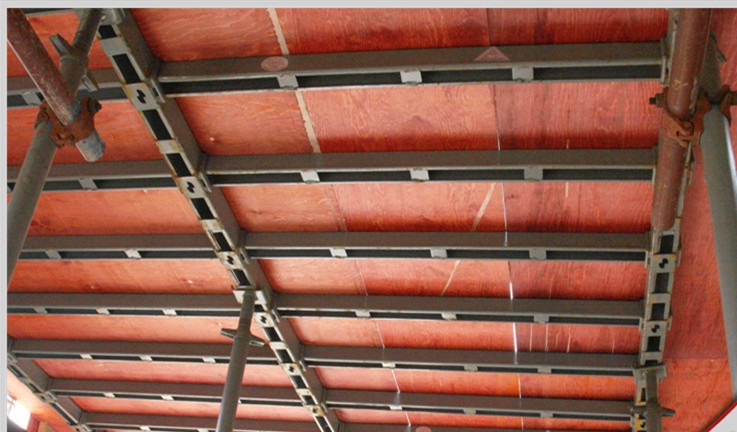
Steel pipe supports shall be of minimum diameter of 80mm.
Accuracy of Formwork
Marking of boundary line of all elements is necessary for the assembling of formwork, level of concrete pouring is also marked on the shuttering.
Whenever concrete pouring joint is available, that joint should be located at middle of span of beam, girder or slab, the joint shall be made by wire mesh with spacing 5mm to 10mm of diameter 0.5 to 1mm.
For foundation and underground beam: Both in horizontal form line and spacing element depth; tolerance is ± 5mm.
For superstructure, general tolerance is ± 3mm.
In case after concrete work, if formwork is deformed over above mentioned tolerance; responsible subcontractor will repair if the deformation occurred is not acceptable.
Reinforcement steel bar Fixing
Rebar shall be free of rust, oil, straight and being of correct type as item specified.
The rebar work shall be executed according to working drawing, typical detail specification drawings, this construction method and quality control procedures.
Rebar processing (cutting and bending) is to be done at the workshop at the construction site, provided that cutting of re-bar should not use gas or welding.
Reinforcement Steel bar Assembling
Steel rebar assembling process shall be done in accordance with the instruction and details of the re-bar list.
According to order of assembling between elements in connection, re-bar assembling can be made either at site in place of element or pre-assembled at the workshop.
Temporary working stage or structure for assembling shall be planned and prepared before hand.
Spacers Provision
All reinforced concrete elements shall be provided with spacers, which includes 2 types as following:
- Spacers for concrete covering depth.
- Spacers for keeping distance of separation between layers of re-bar.
Spacers for concrete covering depth shall be ready made product ( by steel, plastic, for column, beam and girder side covering and upper layer of slab) or by mortar with wire to tie to the re-bar.
Mortar made spaces shall have a period of curing of as least 7 days before being used to keep concrete covering depth of elements.
Spacers shall be arranged correctly as to ensure the covering depth of concrete for the element in concern, being fixed tightly and with strength enough to keep it safe during concrete pouring and compaction process.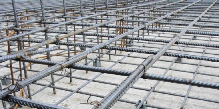
Distance between spacers is varied from 1,000mm to 1,200mm for all elements but according to the shape of element and dimensions, at least 2 spacers shall be arranged for one side, additional spacers shall be put at intersection between beams and with column.
Control of Work
Marking line shall be checked before the formwork, including marking for center line purpose and marking for formwork (form boundary line).
Engineer in charge should supervise the work following all requirements of this method, together with technical parameters and details indicated on working drawings.
Before concrete placing for any element, inspection shall be made with general checking, in which, form work is included.
Health and Safety
Material shall be arranged in order and safety passage shall be provided.
Safety regulations and rules at site are applied also to formwork.
Before support and form removal, warning board shall be provided around working area, removed form and support shall be arranged and cleaning work should be made immediately.
Daily cleaning shall be done by sub-contractor to ensure the site completely clean in the working area.
Concrete Work Method
The concrete used to structure shall be ready mixed concrete. Concrete shall be ordered in accordance with the specified design strength, being subject to quality control as indicated herein.
Transportation of concrete
Mixing trucks shall be cleaned thoroughly after completing each concrete supplying trip. Remaining hardened concrete or any foreign material inside concrete compartment must be cleaned out.
Time of transportation from the batching plant to site shall not exceed 02 hours (otherwise truck of concrete shall be returned to the batching plant).
Record of each mixing truck shall be made.
Any segregated concrete or any defective concrete shall be rejected.
Preparation of Concreting Activity
General Inspection before concrete order shall be done client/consultant engineers, The inspection shall include:
Reinforcement steel bar and anchorage, in accordance with Re-bar list and all relevant specifications.
Form work, including necessary temporary stage or scaffolding for concrete casting.
Confirmation of embedded electromechanical devices and location. Also during concrete casting, these MEP services condition shall be checked by subcontractor.
Before concreting, the moist condition shall be provided to all form work and to previous construction joint surface with water spraying.
Before concreting, tools, equipment’s, electric power supply and labor shall be kept stand by on site.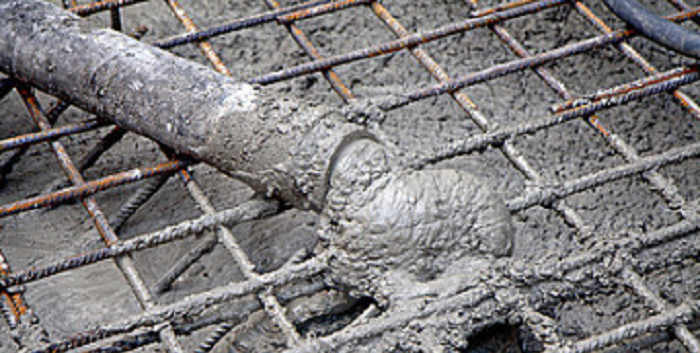
The use of other concrete transportation means, (concrete pump, buckets, chutes) shall be planned and all these equipment’s shall be cleaned and sprayed with water before use.
Top level of concrete to be cast shall be made by marking on form with nail or red adhesive tape (at interval of 1,500 ~ 2,000mm).
In case of slab concrete, level shall be used for checking.
Construction joint:
Construction joints for slab shall follow specifications and structure drawings.
The constructions joint for beams shall be located at 1/3 of span in concern; for columns, it shall be the bottom level of beams.
Any previous construction joint surface shall be cleaned and free of laitance, being roughened with wire brush before the next concrete.
Concrete casting Procedure
Concreting process shall be done continuously until all the planned casting finishes.
In all cases, the height of concrete drop position to concreting place shall be less than 1.5 meter, otherwise a chute shall be used or intermediate height casting opening shall be made.
The concrete shall be vibrated properly. Interval of vibration spot is about 600mm and duration of operation is about 20 seconds.
For long and thin element, combination of vibration and tapping of form work shall be used.
Concrete Curing:
The new cast concrete surface shall be protected by keeping it completely free of any load for at least 24 hours after the completion of concrete pouring.
For concrete curing and marking work, entering cast area is allowed after 01 day. But concrete surface shall not be loaded with any kind of material, equipment, machine or tool until concrete curing is finished.
In case of rain just after concreting, concrete surface shall be protected by vinyl sheets.
The moist condition shall be kept to concrete surface by water spraying at least 2 days after casting to avoid quick hardening.
Concrete defect treatment:
Laitance (if any) on concrete surface shall be taken out for the next concrete or for finishing work.
After removal of form, concrete surface shall be checked. If any defect exists (honeycomb, cold joint, unusual drying out ), it shall be reported.
After consulting with consulting engineer, it shall be repaired immediately with proper approved concrete repair method.
Quality control for Concrete Work
Before casting concrete, general checking shall be done including form work, rebar, levels and cleaning.
During casting concrete, any movement of form and rebar shall be checked carefully.
During trowel of floor surface, the top level shall be checked at all times.
Slump Test: Before casting concrete, the concrete slump must be checked and recorded. (frequency: at the same time that test cube sample is taken)
Concrete temperature checking: Before casting concrete, concrete temperature shall be checked with thermometer and recorded. (frequency: at the same time that slump test is done)
Sample and Compressive Test
Basically the sampling is prepared for every 150m3 of cast concrete. However, for main elements of building, concrete samples shall be taken on every concrete casting.
Sample making, curing and testing shall be done by concrete supplier with instruction of consultant engineer.
Concrete samples shall be cured in curing water tank on site until the day of test.
Curing condition (water temperature, cleanliness) shall be maintained properly. The information of casting (date, building, element) must be indicated on each sample surface.
Compressive test for 7days age shall be done by concrete supplier at their laboratory.
Health & Safety During Concrete Works
Material shall be put in order; safety passage shall be provided.
Safety regulations and rules on site are applied also to concrete work.
Daily cleaning shall be done by subcontractor to ensure the site completely clean in the area of working.
Steel Structure Works Method
Stock yard must be prepared before unloading of steel structure materials.
All steel structure materials are carefully checked and loaded to ensure safe delivery and to avoid shortages.
Materials are packaged and can be unloaded by use of heavy duty Forklift or by crane.
Materials should be laid out in order.
The layout will depend on size of building and site conditions.
Use timber blocks between bundles or members for ease of handling.
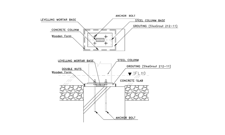
Steel Erection Method – Anchor Bolt Setting
Step 1: Marking for boundary line of starting column on footing.
Step 2: Check and adjust position of starting column-rebar if necessary.
Step 3: Set form for starting column and support them carefully.
Step 4: Marking for bolt-group-center line on side of form.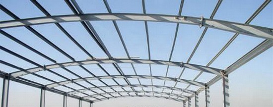
Step 5: Set template with anchor bolts. The template position is higher than concrete surface level. Marking line of bolt-group-center and each bolt must be matched on the template. Adjust position of the template according to marking line on footing by plum bob.
Step 6: Welding diagonal supporting bar to column rebar and anchor bolt.
Step 7: Check position of anchor bolt again.
Step 8: Protect bolts head by masking tape
Step 9: Cast concrete for starting column
Step10: After casting concrete, re-check anchor bolt position. Adjusting the template if necessary.
Steel Structure Erection Step 1:
- Set up 2 side columns of braced bay , including bracing beams.
- Erect interior columns with temporary bracing.
- Tighten anchor bolts and nuts sufficiently to prevent columns from rocking.
- Assemble rafter components on the ground into connection.
- Install all bolts in rafter splices to proper tension, using turn-off- nut method and torque wrench.
- Raise the first assembled rafter on top of column by cranes.
- Install bolts of rafter through column connection and tighten to snug position.
- Secure all temporary, wire ropes bracings, plumb and align the column and rafter before releasing the crane.
Steel Structure Erection Step 2:
- Using same procedure to assemble other parts of the rafter of grid.
- Place it on top of interior columns.
- Bolt to column connections and tighten.
- Secure temporary bracings.
Steel Structure Erection Step 3:
- Assemble the rafter.
- Connect and bolt to column splices.
- The crane has to keep holding the rafter in position until sufficient purlins ( 1/3 of total purlins at that area ) have installed to provide rigid support for the bay.
- The crane can release if having temporary bracing cables for both sides at interval of maximum 10 m.
- Continue erecting the next rafters of the brace bay.
- While completing purlins, flange braces, roof bracings, portal bracings, & strut beams.
- Plumb and align before proceeding to erect the next bays.
- After checking the alignment and square-ness, tighten again anchor bolts, column connection, girts bolts, and eave strut bolts to required tension by torque wrench.
Steel Structure Erection Step 4:
- Continue erecting columns rafters for the next bays, using same procedure described in Step 1.
- Complete installation of purlins and girts.
- Complete roof angle bracings, and all secondary members.
Steel Structure Erection Step5: Fabrication and installation of metal desk panels.
Quality Control for Steel Structure Works
Inspection is necessary at all steps of erection process, from the time of materials received until the structure is completely installed.
Inspection during the erection process shall be continuous in order to prevent the occurrence of possible damage and to maintain high standard workmanship.
Inspection shall include members, painting, connection, alignment, bracings, roofing and wall cladding, equipment and false work.
Inspection of Members
Inspection members for damage due to mishandling or careless storage.
Make sure that each member is placed in its proper position in the structure and that fillers, shims, and washers required for the type of connection are properly used.
Prevent abuse of material by bending, straining, or heavy pounding by sledges.
Inspect the accuracy of match-marked connections.
Check the painting work.
After finishing the painting work, all steel members shall be checked to make sure that complete area of steel members is painted.
Connection Procedure
Anchor bolts:
Check the tolerance of dimensions between anchor bolts to meet the required tolerance (5mm).
Check the tightness of anchor bolts to meet the required forces.
Bolts connection:
The supervisor has to assure himself that the wrenches used are calibrated properly so that bolts are tightened at proper torque levels.
Also the proper lengths of bolts shall be checked.
After connecting, all bolts shall be tightened to obtain the required tension values.
Using turn-off nut method: Tighten more120o+/-30o for bolt diameter >12mm, tighten more 60o-0+30o for bolt diameter = 12mm.
Torque wrench: the actual value must be within the recommended value +/- 5_10%.
Alignment
After completing the erection of main frames the alignment check shall be done again, before continuing the erection of the successive bays.
The tolerance of column plumb must be within the value of 1/500 of column height, but can not be more than25mm.
The tolerance of Rafter alignment (from straight rafter – line) must be within the value of 1/300 of Span.
After completing the erection of main frames, the final check of alignment (plumbing and straightness) for the all columns and rafters of whole building shall be done.
Adjustment of bracing
Adjustable diagonal bracing is fixed after all parts of the structure are in place.
In bolted structures having diagonal bracing, wall bracings are adjusted after the columns are plumbed, and roof bracing are adjusted when rafters are in straight line.
Final Inspection
After completing all trims and accessories, a final inspection of the building shall be done:
All bracings in position and tightened.
All bolts in place and high strength bolts tightened to correct tension value.
Check that roof and gutters are clear of debris and ferrous metals.
Check improper drilled screws.
Check opening for joinery.
Touch up any damaged paint.
Steel Column Base Treatment
Cleaning of concrete column top surface.
Marking centerline of steel column.
Leveling mortar base (using high grade mortar G150) at middle of 4 anchor-bolts with the same level of bottom of column-base-plate.
Checking level of column.
Grouting mortar for column base. (Sika- grout 212-11: refer catalog)
Health and Safety Steel Structure Works
Each workers shall be physically qualified to perform the duties to which he is assigned.
Workers shall always wear hard helmets, shoes, uniforms and gloves.
Workers shall wear safety belts.
Goggles, face masks shields or helmets are required for scaling, grinding, cutting, and welding operations.
Maintenance of machines used in the erection work shall be done properly.
Setting of safety rope on Roof when carry out the roofing work.
Setting of signboard, and barricade by ropes around working area, do not permit any person without duty to enter the working area.
The crane condition (including machine parts, wire rope) must be checked everyday.
Safety meeting shall be done everyday before starting work.
Scaffoldings shall be arranged properly.
Daily cleaning shall be done everyday.
Discover more from Project Management 123
Subscribe to get the latest posts sent to your email.