Below is a comprehensive list of different inspection requirements for receiving storing and installation of different mechanical/HVAC equipment’s.
These inspections must be completed throughout the project at its different stages i.e. delivery, storage, installation & pre-commissioning before the functional testing occurs.
Delivery Inspections
Once the equipment i.e. FCU arrives at the site, usually delivered by a transport company, the following should be checked with the driver before being accepted into storage. Any noted damage should be reported to the manufacturer/supplier within 3 days in writing, supported with photographs.
Supplier’s consolidated delivery ticket is available, showing all equipment and ancillaries for inspection and being used to check.
Copy of the order issued to the supplier is available for reference and is being used to check.
Equipment is packaged and crated in separate boxes for maximum protection.
The unit nameplate and details match the purchase order.
Delivery protection is dry.
Unit/s are dry internally.
The external casing of the unit/s are undamaged.
All pipework connections are the correct size.
Pipework connections are undamaged.
All pipework handing’s are correct.
Make sure that ducting connections are of the correct size
All ancillaries [valves, actuators, dampers, filters] included in delivery as per the order and delivery note
Spin the fan blades to ensure not damaged and out of line
Check all coils for damage externally and internally
Check drip pan/condensate pan for damage, including insulation.
If purchased, check plenums for damage and ensure they are the correct sizes & spigots.
Replace any protection that has been removed.
Storage Inspection / Storage Area
If the equipment is to be placed into storage on site before installation, there will be an inspection completed checking the following for the storage area.
The area is internal and will not be affected by the weather. [If the unit is not rated for external use]
Surface where the equipment is to be placed is flat.
The equipment will be raised from the floor to allow airflow and stop the risk of water ingress.
Area is well covered and protected.
The area is well ventilated and has no risk of high humidity.
Storage area is clean & dust free.
Prior to the units being placed into storage, the following should be checked.
Units will not be stacked.
Units will not have materials stacked on them.
All ancillaries will be placed in a safe and secure location, so items do not go missing or get damaged.
All original packaging is intact and not removed.
Pipework caps are not removed.
Ductwork connections are covered to stop the ingress of dirt and foreign objects.
Unit and all components placed on a flat surface.
Pre-Installation Inspection Checks
Prior to the units being installed, the following should be checked.
The slab/wall/base is ready, flat, and level & can bear the weight of the installation and bracketry.
If being installed above an existing ceiling, ensure that there is enough space through the ceiling grid to install the unit and ancillaries.
Room/area is dry and watertight.
The area being installed is not prone to flooding or ponding of water. [ For wall mounted /floor mounted units]
Room/area the unit will be installed into is clean and dust free. If there is dust/construction work, then the unit should be protected.
If the unit has a ventilation supply, ensure it is installed ready for connecting, or the louver has been installed, if direct fresh air.
The installation of the unit will not impede the installation of the condensate trap/pipework, and the pipework run vs. fall required will be achievable.
All connections, pipework/ductwork, etc., can be independently supported and not supported by the unit. The best practice is to install self supporting brackets prior to the connection of the unit.
Ensure that all access doors are clear and not blocked from brackets or other services, where required.
Check to ensure that all connections kits containing – gaskets, bolts, cleats, screws are available to allow bolting up of the equipment and ancillary equipment.
Remove all transport feet and bolts.
Check that all required cabling is available for connection[power/controls].
Maintenance Access Checks
There is enough space allowed around and above/below the unit once installed to perform maintenance and remove components.
All doors can be fully opened, and panels are removed to gain access to the unit.
Check that there is enough space for coils, fans, and filters to be removed and replaced.
If the unit is mounted at high level, confirm that there is a safe manner to remove the parts and components and that there is enough space at high level and at the floor level to allow this.
Pre-Commissioning Inspection Checklist – General
Once the equipment has been installed and prior to the functional testing and commissioning phase takes place, the following will be checked.
Document the information of the unit from its nameplates and cross-reference with the specified information to ensure correct.
Ensure the unit is level.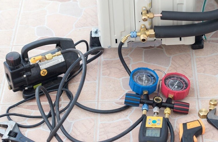
All-access doors/panels can be open and closed with no gaps or leakage.
Check that all transport bolts and feet are removed.
External supply/extract louver, if being used, is installed and fixed with no air gaps.
All vibration mounts installed.
Seismic restraints, where required, installed.
Unit and all components, including valves and controls, are labeled in line with the project naming convention.
Operation and startup manual for the equipment/unit available.
Pre-Commissioning Electrical Inspection Checklist
Unit and components are fully earthed in line with the manufacturer’s instructions.
Earthing has been tested
Emergency disconnect installed for each component in line with NFPA/local code requirements
Electrical voltage from the site matches the unit required voltages.
All cabling is installed and connected on the correct containment/raceways and not damaged.
Cabling has been tested/torque tested.
A local motor control panel [LMCP] has been installed
The local motor control panel has been electrically tested
Electrical cabling is labeled in line with the project naming convention.
Checklist for Controls System/Motorized Dampers & Interlocks
Motorized dampers installed as per the drawings and open/close freely.
All controls and panels have been installed to operate the motorized dampers
Fire trip has been installed and operating/interlocked with the ventilation system.
Ensure all sensors and instruments are installed as per the control logic/manufacturers wiring drawings
Make sure that all the sensors are calibrated.
Checks for Fresh Air Supply [Direct]
This will cover Fan Coil Units that are installed connected directly to the outside to draw in the fresh air.
The position of the intake louver is in line with the design requirements and positioned so as it will not be affected by any exhaust air.
Weather louver/roof cowl installed and weather tight with relevant mesh and is unobstructed.
The weather louver installed with correct mesh.
Weather louver mesh-free area meets the design requirements.
Plenum installed connecting the louver to the ducting.
Plenum has drain installed with trap to remove any unwanted ingress of water.
Plenum has access hatch/s installed to allow future maintenance and inspections.
All fresh air ductwork is installed, correct size, and connected to the unit with correct fixings.
All attenuators are installed as shown on the drawings.
All non-return dampers are installed as per construction drawings.
All volume control dampers are installed as per construction drawings.
Ductwork insulated and vapor seal in line with the specification.
Test holes available in the duct to allow air readings.
Inspection Checks for Fresh Air Supply form AHU
This will cover Fan Coil Units that are installed connected to an AHU system that supplies its fresh air.
The position of ducting is in line with the design requirements.
Plenum installed, allowing the connection of the supply ducting to the ducting.
All fresh air ductwork is installed, correct size, and connected to the unit with correct fixings.
Fresh air has been balanced and providing the correct amount of airflow at the required temperature as per design.
Attenuators are installed as shown on the drawings.
All non-return dampers are installed as per construction drawings.
Volume control dampers are installed as per construction drawings.
Ductwork insulated and vapor seal in line with the specification.
System Fire Dampers: Check that the fire dampers are installed, as per the drawings, and have been tested in line with the project mechanical testing and commissioning requirements.
Filter Inspections
Filter mounting frames are clean and dust free.
Panel filters are installed, clean, and are of the correct grade.
Filters have the correct sealing gaskets installed.
The filters are not jammed in the rails.
All components upstream of the filter are clean and dust free.
Panel filters are locked in place.
Differential pressure sensors are installed and calibrated.
Supply Air Fan Inspection Checks
Electrical connections and cables are complete, fully tested, and torqued in line with project/manufacturer requirements.
Motor protection installed and operating [overload protection].
Motor protections calibrated.
Voltage from electrical systems is correct for the unit requirements [within +/-10%]
The fan housing is clean and dust-free
Fan, blades, and motors are clean and dust-free.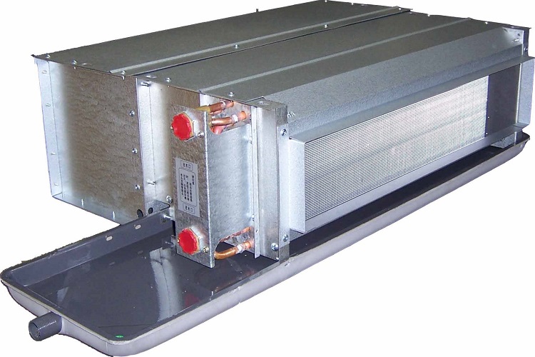
The fan belt tension is correct
Fan belt condition is good
Check the tightness of fixings [torque]
Impeller is balanced
Fan/motor rotates in the correct direction with no obstructions [by hand].
Cooling Coil Inspection Checks
The cooling coil is clean, in good condition, and the fins undamaged.
Check and ensure that the pipework is the connected and correct size.
Ensure that the flow and return pipework handings are correct. [water inlet – downstream of the airflow direction] [Water outlet – upstream of the airflow direction].
Installation of the pipework will not put stress on the equipment connections or create vibrations.
The materials used between the equipment and the chilled water system will not cause Electrolysis.
Pipework that is to connect to the unit has been weld tested.
The pipework that is to connect to the unit has been pressure tested.
Pipework that is to connect to the unit has been cleaned and flushed.
Equipment has been back flushed.
The system has been bled and air removed.
Chilled water system has been hydraulically balanced.
Pipework is insulated and vapor sealed.
Insulation is labeled.
All pressure gauges installed and display scale as per design requirements.
Valves/control valves are installed, and in the correct direction.
Necessary commissioning devices are installed.
All strainers are installed and clean.
Pre-commissioning Checklist for Heating Coil
The heating coil is clean, in good condition, and the fins are undamaged.
Ensure that the pipework is the connected and correct size
Make sure that the flow and return pipework handings are correct. [water inlet – downstream of the airflow direction] [Water outlet – upstream of the airflow direction].
The installation of the pipework will not put stress on the equipment connections or create vibrations.
Materials used between the equipment and the heating water system will not cause Electrolysis.
Pipework that is to connect to the unit has been weld tested.
The pipework that is to connect to the unit has been pressure tested.
Pipework that is to connect to the unit has been cleaned and flushed.
Equipment has been back flushed.
Complete system has been bled and air removed.
The heating water system has been hydraulically balanced.
Pipework is insulated and vapor sealed.
Insulation is labeled.
Pressure gauges installed and display scale as per design requirements.
All valves/control valves are installed and, the correct direction.
Commissioning devices are installed.
All strainers are installed and clean.
Refrigerant Dx Coil System Inspection Checklist
The refrigerant coil is clean, in good condition, and fins are undamaged.
External condenser installed.
Make sure that the gas and suction pipework is connected and the correct size.
Ensure that the gas and suction pipework handing’s are correct.
Installation of the pipework will not put stress on the equipment connections or create vibrations.
The materials used between the equipment and the refrigeration pipework system will not cause Electrolysis.
Pipework that is to connect to the unit has been pressure/vacuum tested.
The system is charged with the correct amount of refrigerant.
Pipework is insulated and vapor sealed.
Check that insulation is labeled.
All solenoids installed and operating.
Recommended sight glasses are installed.
All valves/control valves are installed and, the correct direction.
Inspection Checklist for Condensate drain/siphon
The condensate is installed to the correct fall.
Ensure it is protected from any frost with insulation and/or heating cable.
There is a trap installed and is installed in line with manufacturers’ requirements.
If there are multiple coils installed on a unit, ensure the condensate pipework configuration is installed in line with the manufacturer’s requirements.
Check that the size of the condensate is correct.
Ensure the trap is filled to the correct level.
Ensure the drain pan is clean and free of debris
Electric Heater Inspection
Operation of the heating coil is fan controlled/interlocked.
Fan delay incorporated into the control’s logic, allowing the fan to run [15 mins] after the heater has deactivated/switched off.
Heater elements are clean and not obstructed by debris.
All electrical testing was completed, including torque tests of connections.
Mandatory safety components are connected and operational, including all thermostats to cut power to the heater if needed.
All controls cabling is connected and installed in line with the manufacturers/design drawings.
Power is available to the electric heater/control panel for operation.
Inspection of Supply Air Ductwork from FCU to Grills
All supply air ductwork is installed, correct size, and connected to the unit with correct fixings.
All attenuators are installed as shown on the drawings.
All volume control dampers are installed as per construction drawings.
Ductwork insulated and vapor seal in line with the specification.
Test holes available in the duct to allow air readings.
Return Air Ductwork Inspection
The position of recirculation grilles is in line with the design requirements and positioned so as will not be affected by the fresh air intake. [Be mindful of short cycling]
Plenum installed connecting the grilles to the ducting/fan coil unit.
The plenum has access hatch/s installed to allow future maintenance and inspections.
All extract air ductwork is installed, correct size, and connected to the unit with correct fixings.
Attenuators are installed as shown on the drawings.
All non-return dampers are installed as per construction drawings.
Volume control dampers are installed as per construction drawings.
Ductwork insulated and vapor seal in line with the specification.
Test holes available in the duct to allow air readings.
Discover more from Project Management 123
Subscribe to get the latest posts sent to your email.