Below is a brief mechanical HVAC method statement that covers the installation of chilled water CHW piping system.
This procedure defines the method used to ensure that the piping installation has been carried out as per contract requirements and best practices.
Also it gives details of how the work will be carried out and how health and safety issues and controls shall be implemented as per the relevant risk assessment.
Tools & Equipment
Below is list of necessary tools and equipment that are mandatory for doing the CHW piping installation work. All tools and instrument shall be of proper quality, safe for use and with valid calibration certificate as applicable.
- Spirit Level
- Cutting Tools.
- Measuring Tape, marker
- Screwing Machine & Welding Machine
- Grinding Machine
- Cutting set
- Rub around
- Hacksaw
- Pipe clamp
- Wire brush
- Plumb
- Tube level
- Chalk line
- Hand pump with flexible hose and fittings
- Pressure gauge
- Spanner set, including torque wrench
- Adjustable pipe wrench
Roles & Responsibilities
Project manager shall be responsible overall to complete all MEP works as per specifications, budget, time, & quality.
MEP Site Engineers shall be responsible for but not limited to the following important activities:
To ensure that all the preparation and application works are carried out according to the contract specification and manufacturer’s data sheet(s).
Ensure that the progressing of works is carried out according to the planned program, and as per the approved method statement.
To ensure that all the equipment’s and materials required in executing the works are available according to the planned construction program.
Coordinate with the main contractor’s MEP coordinator and safety officer for all safe and proper execution of the work in accordance with the risk assessment.
To coordinate with the civil team for any area preparation, access, clearance.
Foreman shall be responsible for but not limited to the following important activities:
To guide and control the tradesmen and charge-hands(s).
Ensure that work is done as per the approved shop drawing(s).
To report to the MEP site engineer all issues.
Health and Safety officer shall be responsible for but not limited to the following important activities:
Ensure health and safety of the site personnel.
Ensuring PPE available with site personnel
Good housekeeping on site.
Environmental concerns are addressed.
Responsible for implementation and assurance of the safety and environmental requirements (JSEA).
QA/QC Quality Control Engineers
He shall be responsible for but not limited to the following important activities:
Inspecting the materials on site as per approved materials submittal prior to installation, then raise MIR to the Consultant for material approval.
Inspection for the installation as per approved drawings and approved test plans and checklists.
Preparing test forms for testing on site and updating results
Issuing inspection request to the consultant for installation approval within 24 hours before the actual inspection.
Responsible for the assurance of Quality control, method statement and inspection test plan.
Controlling the shop drawings flow on site.
CHW Piping Material Handling Storage & Transportation
Pipes will be transported to the site by the supplier. Care must be taken to ensure the pipes are evenly supported throughout their length and should not overhang the vehicle bed by more than one meter. Pipes should be loaded with protective fittings at alternate ends.
Larger pipes must be loaded first and if the vehicle is fitted with side supports, these shall be on height not greater than 1.5 meter. Any supports must be free from sharp edges to prevent damage of the pipes during transportation.
Pipes should not be dropped onto hard surfaces and should not be dragged along the ground. Where possible the loading and unloading of pipes should be carried out manually by hand.
If mechanical lifting equipment is to be used, no metallic slings, hooks or chains should be used in direct contact with the pipes.
To ensure that deterioration of the pipes and fittings does not occur during storage, it is imperative that the following recommendations are adhered to:
Pipes supplied by the factory in bundles should be stored on a flat surface. Bundles should not be stored on top of each other.
The pipes should be stacked on a flat surface free from sharp projections, stones or other protuberances likely to cause point loading or pipe deformation.
Side supports should be provided in the form of stout timber posts, not less than 75 mm2 placed at no greater than 1.5 meter centers along the length of the pipe. The width of stacked pipes should not exceed 3 meters.
The height of pipe stacks should not exceed seven layers or two meters maximum height.
Stacks should be protected from weather elements by means of placing tarpaulins or similar sheets over them securely fixed to the timber support posts, in order to provide protected and shaded conditions and at the same time allow a free passage of air around the pipes.
Inspection of Materials in Store
Notify MEP Engineer upon delivery of material at site store.
All materials shall comply with the approved material submittal.
Upon the receipt of materials on site, these shall be inspected by the QC Engineer / Inspector to ensure correctness of material as the approved material submittals and quantities.
Ensure that the materials are handled properly, and protected against dust, dirt and foreign matter.
A material inspection report (MIR) shall be prepared by QA/QC Engineer / Inspector for submission to the consultant for review and acceptance.
Material not complying with the Material Submittal or unusable/damaged pipes or fittings will be placed in a quarantined area and clearly labelled ready for manufacturer to replace.
Chilled Water Pipe Installation Methodology
The CHW piping installation works shall be executed in accordance with the following methodology and sequence.
Pre-installation checks
A pre-start meeting prior to the commencement of the works will take place with the Site Engineer, H&S Officer, QC Engineer, Supervisor / Foreman in charge to address the following:
Ensure that the area has been surveyed as per approved drawings.
Make sure that the installation area is clean from debris and foreign matter.
Ensure that material is as per approved Material Submittal and Contract Specification
Make sure that adequate number of tradesmen and proper tools are present.
Ensure that latest approved shop drawing for the piping installation is present, and all personnel are working off the same drawing.
Check that the area is safe to carry out the chilled piping installation works.
Area for materials preparation / fabrication for piping installation have been identified and procedures will be in place.
Temporary DBs are provided and inspected regularly by the electrician prior to execution of the works.
Piping Installation Procedure
Drawing plans, schematics, and diagrams indicate general location and arrangement of piping systems. Install piping as indicated unless deviations to layout are approved on Coordination Drawings.
All piping installation shall be in concealed locations, unless otherwise indicated and except in equipment rooms and service areas.
Install piping indicated to be exposed and piping in equipment rooms and service areas at right angles or parallel to building walls.
Diagonal runs are prohibited unless specifically indicated otherwise.
Install piping above accessible ceilings to allow sufficient space for ceiling panel removal.
Install piping to permit valve servicing.
Install piping at indicated slopes.
Install piping free of sags and bends.
Install fittings for changes in direction and branch connections.
Install piping to allow application of insulation.
Select system components with pressure rating equal to or greater than system operating pressure.
Install groups of pipes parallel to each other, spaced to permit applying insulation and servicing of valves.
Install drains, consisting of a tee fitting, DN 20 ball valve, and short DN 20 threaded nipple with cap, at low points in piping system mains and elsewhere as required for system drainage.
Install piping at a uniform grade of 0.2 percent upward in direction of flow.
Reduce pipe sizes using eccentric reducer fitting installed with level side up.
Unless otherwise indicated, install branch connections to mains using tee fittings in main pipe, with the takeoff coming out the bottom of the main pipe. For up-feed risers, install the takeoff coming out the top of the main pipe.
Install strainers on supply side of each control valve, pressure-reducing valve, solenoid valve, in-line pump, and elsewhere as indicated. Install DN 20 nipple and ball valve in blow down connection of strainers DN 50 and larger. Match size of strainer blow off connection for strainers smaller than DN 50.
Anchor piping for proper direction of expansion and contraction.
All the products intended to use for this project shall be seismic (zone-2a) complaint as per applicable authority regulation.
Install sleeves for pipes passing through concrete and masonry walls and concrete floor and roof slabs.
Install sleeves for pipes passing through concrete and masonry walls, gypsum-board partitions, and concrete floor and roof slabs.
Cut sleeves to length for mounting flush with both surfaces.
Exception: Extend sleeves installed in floors of mechanical equipment areas or other wet areas 50 mm above finished floor level. Extend cast-iron sleeve fittings below floor slab as required to secure clamping ring if ring is specified.
Install sleeves in new walls and slabs as new walls and slabs are constructed.
Install sleeves that are large enough to provide 6.4 mm annular clear space between sleeve and pipe or pipe insulation.
Use the following sleeve materials:
Steel Pipe Sleeves: For pipes smaller than DN 150.
Steel Sheet Sleeves: For pipes DN 150 and larger, penetrating gypsum-board partitions.
Installation of Pipe Supports
Marking for alignment & coordination to be done prior to fixing of anchors.
Attachments to the roof slab will be by the means of expansion anchors.
Drill into the concrete and place the expansion anchor.
Threaded rods and channel sections will be prepared for installation in the workshop.
Building attachments: insert the powder coated actuated fasteners or structural steel fasteners appropriate for building materials and all cutting edges shall be cut and painted with specified paint.
Also need guides, roller supports as required.
For full details regarding hangers and supports requirements refer to the “Hangers & Supports” method statement.
Piping Joint Construction
Ream ends of pipes and tubes and remove burrs. Bevel plain ends of steel pipe.
Remove scale, slag, dirt, and debris from inside and outside of pipe and fittings before assembly.
|
Chilled Water Black Steel Pipes Joining Method Schedule |
|||
|
No. |
Area | Size | jointing Method |
|
1 |
Horizontal Lines | DN 50 and Smaller |
Threaded Joints |
|
2 |
Horizontal Lines | From DN 65 to DN 900 |
Grooved and/or Welded Joints. |
| 3 | Risers | All Sizes |
Welded Joints |
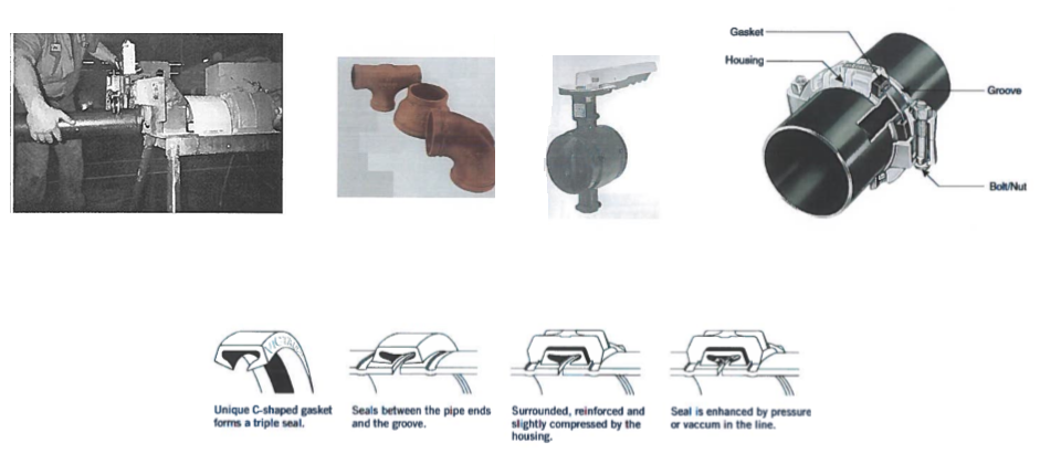
Grooved joints: Apply on black steel pipes for sizes – 65 mm and above as per manufacturer’s instructions.
Grooved systems are fast, clean, dependable, and are alternate ways of joining pipe as opposed to welding, threading, flanging, and soldering.
Grooves are rolled or cut into the ends off the pipe.
Fittings, valves, and other components are manufactured with the same grooves.
Couplings with pressure responsive gaskets and shoulders to fit the grooves are used to join grooved pipe to grooved pipe or grooved components.
Threaded Jointing Method for Pipes
A threaded pipe is a pipe with screw-threaded ends for assembly.
Use a manual pipe threader machine.
Workshop area to be kept clean & be provided with thick Polythene sheets below to avoid grease / oil marks on the shop floor.
Attach a die head to cut the thread.
The pipe threading machine will be used to thread the end section of the pipe.
Inspect the pipe threader before beginning and replace dies or any parts that show signs of wear.
Worn or damaged dies can result in poor thread quality.
Mount the pipe firmly in the pipe vise by placing it in the vise and then tightening until it is held tightly.
Cut the end of the pipe cleanly and squarely by using a pipe cutter.
If you have an industrial pipe threader with cutting capability, use the machine to cut your pipe to length.
Pipe cutters come with guides, which provide square alignment.
The pipe cutter will have a thin cutter wheel, which will slice through the pipe as you guide it in the space.
Be sure to wear goggles and protective gear. Steel may produce sparks.
Ream the cut end of the pipe to remove any burrs from the cut using a reamer, which is a cylinder-shaped rotary cutting tool that you run smoothly across the freshly cut edges of the pipe to remove rough edges.
Select die head according to the size and type of pipe being threaded and the thread form required.
Die heads come in different shapes and sizes that include different threads for pipes that have different diameters.
Place the die head over the pipe on the threader.
Press steadily on the front of the die head, while simultaneously pushing the handle down to start the threader.
Before placing too much pressure on the handle, check to be sure the ratchet pawl is engaged.
Use your weight as leverage to apply pressure on the handle, while holding it firmly.
Be sure to maintain proper footing and balance for maximum control.
Never use a tool or mechanism to hold the handle in place in order to free your hands. This can be dangerous and could result in injury.
Apply threading oil generously while threading.
Using oil too thin as a substitute for threading oil can result in sub-standard threading.
Stop threading when the end of the threading die is flat against the end of the pipe.
When the die is even with the pipe that means the correct threading size has been reached, pushing after this point, will damage the thread.
Reverse the ratchet mechanism and turn the die head in the opposite direction.
Be careful to maintain control of the threader as the dies are removed.
Threads can become damaged when the die head is being removed if you don’t maintain control and move the piece smoothly.
Hard wired brush to be used for removing burrs.
Stand the pipe on end and gently tap it to remove any particles that may be lodged within. Clean the pipe with a cloth, removing any oil.
While handling be careful, the thread edges are very sharp.
Seal the threading with Teflon tape or a pipe thread compound when attaching the pipe to the connector.
Clean the pipe threader machine thoroughly after use so the oils and metal pieces do not damage the machine, which could cause sub-standard threading during next time.
Damaged Threads: Do not use pipe or pipe fittings with threads that are corroded or damaged. Do not use pipe sections that have cracked or open welds. Contractor to provide any transitions required for threading piping between ASME and British Standards.
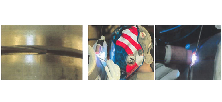
Method of Welded Joints
Cylinders to be stamped for validity to use on site with proper storage & maintenance.
Cut the end off of the welding wire protruding from the welding tip of the MIG welder with the wire cutters.
Back spool the welding wire to remove the wire from the MIG gun and lead.
Remove the spool of wire.
Spool the MIG welder with the 309 welding wire.
Exchange the gas with the three part shielding gas mixture.
Before attaching the three part shielding gas, lay the gas bottle on its side and roll the tank back and forth for two minutes to ensure a thorough mixing of the gas.
Attach the gas gauges to the three-part gas bottle.
Turn on the MIG welder and set the heat and wire speed.
Mark the pipe with the permanent marker and the pipe wrap. Cut the pipe with the band saw.
Attach the hard grinding wheel to the grinder.
Place a 20-degree bevel on end of the cut test pieces of pipe with the grinder.
Hold the grinder at a consistent 20 degrees to give you an even fill line.
Take care when grinding the pipe.
Heat builds quickly especially on black steel pipes. The pipe will get hot enough to produce burns in a matter of seconds.
Place one beveled end of the steel pipe against a beveled end of the other steel pipe.
Allow a 1/16th weld gap between the two pieces of pipe. Place a tack in the weld joint to hold the pipe together.
Roll the pipe and place a tack every inch around the entire circumference of the pipe. Ensure that at each tack you hold the 1/ 16th inch weld gap.
Weld the pipes together; roll your MIG gun in a circle to flow the puddle, dropping 1/8th of an inch at each down stroke to create a nice “roll of dimes” weld.
Watch the bottom of the weld to ensure proper penetration.
If the carbon pipe is under-cutting, reduce the heat on MIG welder and try again. When reducing the amount of heat fails to reduce the undercut, quicken the up stroke of circle to pull the heat away from the steel pipe.
|
Summary Table of Pipe Welding Electrode |
|||||||||
|
GB |
AWS | Type of Coating | Current |
Main Applications |
|||||
|
E4310 |
E6010 | High Cellulose Type | DC+ |
Used for butt welding of circumferential seam on all kinds of carbon steel pipes, and also suitable for vertical downward welding on general carbon steel structures. |
|||||
| E5010-G | E7010-G | High Cellulose Type |
DC+ |
Used for butt welding of circumferential seam on all kinds of carbon steel pipes, and also suitable for vertical downward welding on general carbon steel structures. | |||||
|
E5510-G |
E8010-G | High Cellulose Type |
DC+ |
Used for filling and cosmetic welding of carbon steel and low-alloy steel pipelines with the same strength grades, and also suitable for vertical downward welding on general structures with the same strength grades. | |||||
|
E5048 |
E7048 | Low- hydrogen
Type |
DC+ |
Suitable for downward welding, downward fillet welding and downward butt groove welding on round pipes with thickness lower than or equal to 9mm, and also used for downward backing weld on round pipes with thickness higher than 9mm. | |||||
|
E5015 |
E7015 | Low- hydrogen Type |
DC+ |
Suitable for downward welding, downward fillet welding and downward butt groove welding on round pipes with thickness lower than or equal to 9mm, and also used for downward backing weld on round pipes with thickness higher than 9mm. | |||||
|
E5518-G |
E8018-G | Low- hydrogen Type |
AC, DC+ |
Suitable for filling welding and cosmetic welding on medium-carbon steel and low-alloy steel pipes with corresponding strength grades, and also used for downward fillet welding and downward butt groove welding on structural steel with the same strength grades. | |||||
Procedure of Flanged Joints
A flange is an external or internal ridge, or rim (lip), for strength, as the flange of an iron beam such as an I-beam or a T-beam; or for attachment to another object, as the flange on the end of a pipe, steam cylinder, etc., or on the lens mount of a camera; or for a flange of a rail car or tram wheel.
Thus flanged wheels are wheels with a flange on one side to keep the wheels from running off the rails.
The term “flange” is also used for a kind of tool used to form flanges.
Pipes with flanges can be assembled and disassembled easily.
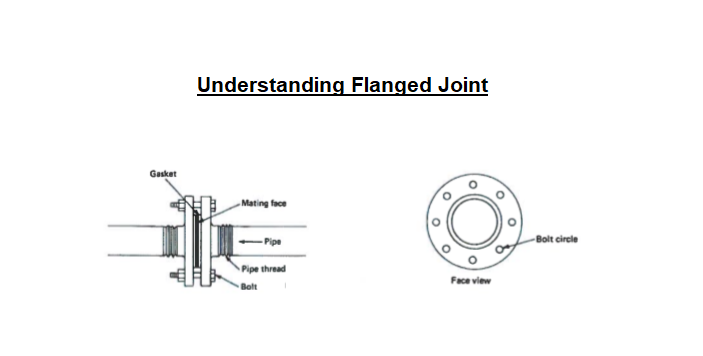
Important points to be taken in consideration when installing a flange connection:
Select appropriate gasket material, size, type, and thickness for service application.
Gasket selection to be also based on pressure being applied in pipe.
Install gasket concentrically positioned. (gasket should be one piece)
Use suitable lubricants on bolt threads.
The flange Pressure Rating (PN) must be suitable with the system pressure.
Piping Connections
Make connections according to the following, unless otherwise indicated:
Install unions, in piping DN 50 and smaller, adjacent to each valve and at final connection to each piece of equipment.
Install flanges, in piping DN 65 and larger, adjacent to flanged valves and at final connection to each piece of equipment.
Wet Piping Systems: Install dielectric coupling and nipple fittings to connect piping materials of dissimilar metals.
Flexible Joints
Provide flexible connectors at all pumps, chillers, fan coil units, air handling units, head exchangers, condensers and cooling towers.
Elastomeric flexible connectors may be provided as expansion joints in chilled water piping at set intervals (not exceeding 18m), ensuring that thermal movement at any joint does not exceed the allowable axial movement of the connector.
Construction of flexible connectors shall be Neoprene inner tube and outer cover with multiply nylon tyre cord fabric reinforcement.
Standard duty flexible connectors shall be rated for 1600kPa working pressure and 2400kPa test pressure, up to 105°C.
Manufacturer shall certify that each unit is individually pressure tested.
Connectors for pipe size 65 mm and above shall be of spherical single bellow design with captive steel floating flanges to facilitate alignment.
Flanges shall be epoxy powder coated.
Bellows shall have steel wire reinforcement at the lips.
Connectors for pipe size up to 50 mm shall be of double bellow design with threaded ends.
End connections shall be triangular flanges made from forged steel and epoxy coated. Ml unions will not be accepted.
Connectors for FCUs shall be as above, but with a bronze coupler at one end, suitable for direct threaded or brazed connection (as required) to the FCU header.
Usage of flexible hose/ SS braided hose for FCU connections will not be accepted.
Where flexible connectors are connected to unanchored piping or isolated equipment, provide control units when pressure exceeds the maximum recommended for this application by the manufacturer.
Air Vents Installation
Air Vents shall be installed on all coils, at all high points of piping inside and outside plant rooms, at the head of vertical rises and other high points required for efficient operation and venting of system.
Air vents shall be provided at all high points in the pipework, whether indicated on the drawings or not.
Air bottles shall be provided at all venting points.
More specific details regarding Air Vents will be provided separately upon material approval to comply with the supplier requirements and recommendations.
Automatic air vents also to be used as & where required.
Test Plugs Installation
Provide test plugs of solid brass or stainless steel at the following locations, whether indicated on the drawings or not:
- Inlet and outlet of each FCU, AHU, chiller, pump, heat exchanger.
- Across control valves, strainers, regulating valves (2 per DRV), metering stations.
- Take-off and return of piping branch circuits.
Plugs shall have leak proof neoprene twin-core design. They shall be suitable for receiving temperature and pressure probes up to 3.5 mm stem diameter.
Restraining straps shall be present to prevent loss of plug caps.
Plugs shall be rated for 3500kPa working pressure up to 87°C.
Extended body test plugs shall be installed on insulated piping so that plug caps extend beyond the outer surface of insulation.
Tapering of insulation at test plug locations shall be avoided.
Valve Installation
Check for the valve damage, cracks, missing parts and tightness of containing bolts.
Ensure that all valves are as per Valves and Strainers of Specification for Chilled Water Piping.
Check valves for cleanliness of bores and seating surfaces etc. prior to installation.
Ensure valves are closed in position before installation.
To ensure proper functioning operate valves through one complete opening and closing cycle in the position in which they are to be installed.
Ensure to place a firm footing to prevent setting and excessive strain on connection to pipe.
Valves must not be used for aligning miss-aligned pipes.
For full details regarding valves requirements refer to the “Valves & Fittings” method statement.
Installation of ancillary Items
Install automatic (or manual where suitable) air vents at high points in system, risers, main and branches and as required for system air venting as per approved shop drawing where applicable and to be fitted with an 8mm air release pipe which shall terminate such that any discharge will not cause damage or hazard and may be readily cleared to drain.
Install pressure gauges, temperature gauge, test point as specified in approved shop drawing.
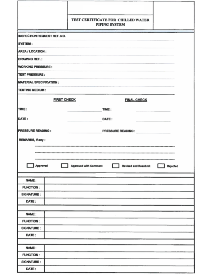
Piping Hydrostatic Pressure Testing Method
The piping system will be subjected to hydrostatic test pressure that is not less than 1.5 times the design pressure for 10 minutes.
Test pressure will not exceed maximum rating pressure for any vessels, pump, valve or other component in system under test.
Ensure pressure test has been conducted and approved prior to chilled water insulation.
After satisfactory lying of pipes, joints will be insulated and cladded in the following manner.
Check the pipe outer diameter.
Ensure the dimensions of field joint including length & diameter of flexible coupling for grooved jointing only.
Clean the surface of the pipe joint and remove any foreign materials around the joint area. Ensure that the joint is clean and dry.
Testing Procedures & Requirements
Make temporary tapping provisions at multiple points for easy and quick filling and draining of water for testing and flushing of the system.
Valve off piping system and disconnect method of piping system pressurization before starting the 2 hour pressure holding period.
During hydrostatic pressure test, examine piping system for leaks.
Repair leaking joints, replace damaged and porous pipe and fittings with new materials, and repeat tests.
Pipe system will be pressure tested in stages at permanent isolating valve locations.
Chilled water piping will be tested to 1.5 times the maximum system working pressure.
The chilled water piping CHW maybe tested in sections, in part or completely depending on site requirements and conditions.
Testing pressure must not exceed the testing pressure of valves and other accessories installed on the piping network.
Fill the system with clean water and continue filling till pressure on the gauge at lowest level indicates pressure equal to 1.5 times maximum system working pressure.
Observe the pressure reading for 2 hours.
When completed raise inspection request to the QA/QC Engineers for inspection and sign-off.
After successful inspection and inspection report been signed off, ensure readiness for system flushing, start-up, and water balancing inspection request to be issued to the consultant for approval.
Keep always in mind checking the quality of the adjustments and of the finishes.
This list is not exhaustive and the engineers may require additional tests to those specified initially in the test program if he considers it necessary.
Discover more from Project Management 123
Subscribe to get the latest posts sent to your email.