This Work Method Statement (WMS) is to describe the method for the CO2 fire suppression system installation & pressure testing for any kind of a project.
The aim and /or benefit of complying with this method of statement includes the project specifications & program compliance, Health, Safety, Quality and Environmental company policy compliance.
All installation at site shall be based on approved IFC drawings, specifications, procedures, codes and standards.
Install fire protection systems in accordance with NFPA rulings, listings and manufacturers recommendations.
Project Engineer / Supervisor will orient and familiarize all the workers and assistants involved in the installation regarding relevant approved drawings, technical submittals, installation procedures, details and acceptance criteria etc.
Codes and References
- Approved Project Quality Plan
- Project HSE Plan
- Approved Material Management Plan
- Project Specifications
- Local Civil Defense Regulations
- NFPA 12 – Standard on carbon Dioxide Extinguishing System
- Approved Material Submittals.
Necessary Tools & Equipment’s
- Pipe Wrenches
- Level
- Hammer
- Chisel
- Spanners
- Torque Wrench
- Screw Drivers
- Saw
- Files
- Third Party Certified Drilling Machine
- Third Party Certified Grinder Machine
- Third Party Certified Threading Machine
- Drip Tray
- Step Ladders
- Aluminum Mobile Scaffolding
- Calibrated Pressure Gauges
- Third Party Certified Chain Block
- Third Party Certified Slings or Lifting Belt
- Third Party Certified Mobile Crane / Boom Loader
Roles and Responsibilities
PROJECT MANAGER
To be the focal point for over all interfaces and other communications with the client, contractor and specialist supplier as required during project execution.
Ensure that adequate quality measures are being undertaken.
He shall identify and secure necessary resources, determining the task that must be completed, assigning the tasks and delegating authority.
Ensure the overall implementation of this procedure.
QA/QC ENGINEER
Ensure all inspections are raised and conducted as per the contract specifications, PQP (Project Quality Plan) & ITP’s.
Make sure that only approved materials, proper tools & tackles and manpower are used at all stages of work.
Check and ensure that approved revised latest versions of procedures, material submittals, shop drawings and standards are available at the point of use i.e. at the construction site.
Ensure that the fire suppression system installation work complies with the contract requirements and approved shop drawings.
Liaise with client/consultant for inspection and approval of the fire safety system installation works.
Inspect for any damage during, handling and storage.
Monitor the quality of workmanship, ensure fulfillment of specified requirements and maintain the necessary records related to the installation and testing activities.
SITE ENGINEER
Follow approved drawings, method statements to carry out the work execution at project site.
Ensuring foremen are well informed about specific work requirements related to co2 fire suppression system.
Coordinate with other discipline site engineers, safety engineer and contractors/sub-contractors for smooth execution of site installation works of fire protection system.
Ensure that all foremen are well aware of safe system of work and following the applicable HSE requirements.
Clear the obstructions from the surrounding area to avoid Near misses and accidents.
Inspect the progress of work until final execution and completion.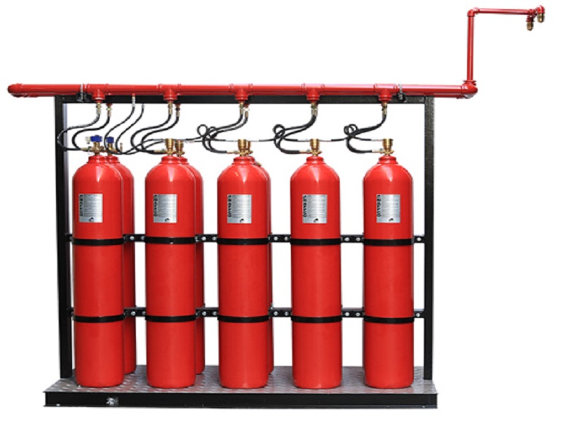
Raise WIR (Work Inspection Request) to get the works inspected as per the quality control procedure.
SITE FOREMAN
Supervise and execute the installation according to the approved shop drawing and method statements.
Coordinate with the discipline engineer for site execution and during final inspection.
He will coordinate with crew on implementation of Safety & Environmental procedures at the site.
SAFETY ENGINEER
Toolbox talk has to be conducted and all the hazards have to be identified and communicated to the workers before starting the work.
To make sure that Personnel Protective Equipment’s (PPE) are available and used by the workers during the fire safety system installation at the project site.
Risk related to the activity shall be assessed and addressed as required using the risk assessment format as per project HSE plan.
To provide necessary HSE training for the work force in order to execute the activity safely.
Carry out regular and random inspections on site and record observations to improve the safety culture at the site.
Material Receiving Storage and Handling
Materials shall be stored inside the warehouse and properly protected as per manufacturer/supplier guidelines.
Storekeeper will receive the material and check for quantity as per Delivery Note, also check any damages or missing items, which shall be recorded in the “Delivery Note”.
In the event of damaged materials same shall be informed to supplier in order to claim replacement.
All pipes shall be stored properly with end caps.
The pipes shall be stored on a flat dry level surface free from sharp projection, stones or other objects likely to cause point loading or pipe deformation.
Timber supports space 1.5 meter apart the pipe can be used to support the pipes.
After successful receiving of material at site, raise the Material Inspection Report MIR for consultant approval, with all necessary supporting records/certificates/reports.
Material Engineer/MEP Coordinator shall carry out initial inspection before the final inspection from client.
After MIR approval and receiving the material requisition note from the engineers or supervisors, storekeeper will arrange the transportation to deliver the material to work place.
The material received at work place will be off loaded by the available manpower or if required Mobile crane or Boom Loader and stored properly at site in clean & dry place with wooden supports.
For materials to be used in upper floors where crane / loader will be used, ensure proper coordination with ongoing works of other trades in the area.
Obtain permit for lifting works prior to start of activity and ensure that barricades are put in place.
Only certified riggers and tradesmen shall supervise all lifting operations.
Fire Protection System Piping Installation Method
Make piping layout and installation in the most advantageous manner possible with respect to headroom, valve access, opening, equipment clearance and clearance for other utilities/services.
Give particular attention to piping in the vicinity of equipment’s, by preserving maximum access to various equipment parts for maintenance.
To support the fire safety system do not cut or weaken any structural member.
Cut all pipes accurately to measurement determined at the site and after cutting the pipe, ream it to remove all burrs.
Install piping neatly, free from unnecessary traps and pockets.
Fit the pipe into the place without springing or forcing.
Use only the approved fittings to make all changes in the co2 piping directions, field bending and mitering are prohibited.
Make all connections to equipment using flanged joints or unions.
Where necessary make reducing connections with reducing fittings only.
Remove dirt, scale and other foreign matter from inside piping before tying in sections, fitting, valves or equipment.
Jointing the Fire Suppression Pipes
Threaded joints shall be made by using the Teflon tape or Jute with a sealing compound applied on male threads only.
Ends of pipes shall be reamed out before being made up into fittings.
Joints in threaded steel pipe shall conform to the American National taper pipe thread, ANSI B1.20.1 or British Standard BS21.
All burrs shall be removed, pipe ends shall be reamed or filed out to size of bore, and all chips shall be removed.
Over threaded pipes and fittings shall not be installed.
Fire Extinguishing System Installation Guidelines
The installation of CO2 Fire Extinguishing system shall be according to the approved detailed shop drawings and also as per the recommendations of NFPA 12.
Pipe supports shall be spaced at intervals not exceeding 15 feet.
All piping must be rigidly supported and pipe supports shall be spaced at intervals not exceeding 15 feet.
Piping shall be supported from steel or concrete structural members.
The fire safety system piping shall be supported and braced to restrict movement due to nozzle reaction so that system performance and integrity is maintained.
Rigid pipe supports are required to support the live load of the pipe system during discharge.
Rigid bracing is required at each directional change fitting, tee and nozzle.
All drops to 180° nozzles require back bracing in the opposite direction of the discharge.
The fire suppression system piping shall be installed in accordance with approved system schedules/plans.
Ensure that any rerouting of pipes due to site condition shall be only carried out after approval.
Pneumatic Pressure Testing of Fire Suppression System
Pressure test shall be performed by specialist and qualified persons/engineers.
Make sure that the plugged connections and nitrogen air compressor connection are installed properly.
Check and ensure that no equipment item such as nozzles are subject to the pressure test.
Make sure that all pipe works are suitably plugged.
Physically check and ensure that all pipes undergoing test are strongly supported and loading of pipe work will not introduce undue stress on any support.
The entire pipe work shall be pneumatically tested for minimum 2 minutes at 600psi (41.36 bars) pressure.
At the end of 2 minutes, pressure drop should not exceed 10 percent of test pressure.
Connect a calibrated pressure gauge.
Connect nitrogen gas cylinder and gradually apply nitrogen gas to increase test pressure to the required level.
Hold the piping under pressure for duration of 2 minutes.
Observe for any leakage or reduction in pressure, if the pressure gauge shows a steady reading after 2 minutes; notify the consultant/client for witnessing the pressure test activity.
Inspection request to be submitted 24 hours prior to the Engineer before commencing the pressure test.
Test that is proven to be unsatisfactory shall be repeated to the satisfaction of the inspecting parties.
Co2 Devices Installation Procedure
Install the prefabricated rack assembly as per the approved shop drawings with using proper bolt/nut/washer/raw shield.
Now install the weighing device to the rack as per the shop drawings.
Install manifold and piping as mentioned in the piping installation drawings/procedure for the CO2 system.
Hang the CO2 cylinder in the weighing device.
Install the flexible hoses and connect to the cylinders.
Install the master actuation kit.
Selector valve to be installed as show in the approved shop drawings and at the proper location.
Install the pressure switch.
Pneumatic operated siren, header safety, header vent plug, weighing panel, odorizer, stop and maintenance valve to be installed as shown in the approved shop drawings.
Approved Warning signs to be provided in the doors of the room protected by CO2 system.
Inspection Checklist for Co2 System Installation
|
1. |
Check the material were delivered and installed as per approvals. |
|
2. |
Check the co2 system is installed according to the approved shop drawings. |
|
3. |
Check the hazard area configuration and area dimensions are according to the approved shop drawings. |
|
4. |
Visually check that all the opening in the hazard is completely sealed. |
|
5. |
Check all co2 cylinders are securely fastened. |
|
6. |
Check that the nozzles are installed according to the approved shop drawings. |
|
7. |
Close the stop/maintenance valve and check the indication in main fire alarm panel. |
|
8. |
Check the connection of the pressure switch |
|
9. |
Remove one of the co2 cylinders to check the automatic co2 cylinders weighing device/panel, and this will cause indication in the co2 cylinders weighing panel and also at the main fire alarm panel. |
|
10. |
Install back the co2 cylinder. Reset the co2 cylinders weighing control module and the co2 cylinder weighing panel and the main fire alarm panel. |
Discover more from Project Management 123
Subscribe to get the latest posts sent to your email.