This air conditioning method statement is developed for any kind of the project in order to achieve best quality of work at all levels for ac installation activity.
Method Statement covers all the critical installation activities of air conditioning systems that includes refrigerant piping installation, brazing and air conditioning unit installation.
Purpose of this procedure is to define the sequence and methodology for all critical installation activities pertaining to the DX type air conditioning units including piping and accessories in the building and the frequency on which the inspections are to be carried out in accordance with applicable specifications, standards and drawings.
ABBREVIATIONS & DESCRIPTIONS
AFC: Approved For Construction
PPE: Personal Protective Equipment
ITP: Inspection and Testing Plan
MSDS: Material Safety Data Sheet
AC: Air Conditioner
HSE: Health Safety and Environment
HVAC: Heating Ventilation and Air-conditioning
QA: Quality Assurance
QC: Quality Control
Necessary Tools and Equipment
Common tools required to carry out the air conditioning installation are: ladders, drill machines, grinders, tool box contain, Hammer, Measuring Tape, Nylon Rope, Rivet gun, Spanner set, Screw Drivers, Spirit Level Indicators, Markers, Drilling Machine, Pipe Wrench, Grooving Machine, Thread Cutting Machine, Pipe work Tools box, Grip Player and other tools not referred here may be indicated under appropriate section of this document.
Split & Packaged Unit Installation Method Statement Package – Download Editable Files
Fork lift or crane with capacity, Hydraulic trolley and scaffolding with platform.
Necessary equipment:
- Vacuum pump
- Vacuum gauge
- Charging bottle (or service cylinder containing refrigerant) (Vacuum pump, vacuum gauge and charging bottle can be assembled as an evacuation and charging board.)
- Charging hoses
- Leak detector
Material Storage and Handling
All construction material specification together with the relevant certificates shall be submitted to client/consultant for approval prior to proceed with the material order.
Need to identify a safe and clean designated storage shelter if the material needs to be stored at site prior to installation on its final location.
The materials requiring proper stacking should be stacked on proper pallets and preserved as per the manufacturer instructions.
Check that the manufacturer protection is sufficient / enough for the storage and transportation and if required, provide additional protection.
Ensure the protection is not disturbed until the material or equipment is opened for inspection / installation.
Any flammable material and chemicals shall be stored as instructed by manufacturer i.e. via Material Safety Data Sheets.
Material safety data sheet (MSDS) shall be kept at easily accessible location of the storage spaces containing chemical solvents, powders etc.
All the material shall be preserved based on the manufacturer recommendation.
Material inspection shall be carried out by QC personnel.
Defective & nonconforming material will be stored separately in a designated area, these materials shall be immediately replaced, repaired or disposed by respective department as per the instruction provided by procurement division.
Split & Packaged Unit Installation Method Statement Package – Download Editable Files
SITE PLANNING AND PREPARATION
ACCESS ROUTES & STORAGE SPACE
Site management shall decide temporary material storage area and control the safe accessible route to the storage area for entry / exit.
Storage area shall be barricaded and labeled properly, and entry into this area shall be restricted to authorized persons only.
Critical material handling activity shall be done in presence of safety officer and the concerned supervisor.
Requirements for Working at Height
Site engineer in coordination with hse engineer shall arrange necessary scaffolding as per the request, scaffolding shall be inspected & tagged prior to release for use.
Dismantling and modifications shall be done by only competent scaffolder as per site requests.
Any work at the height of more than 2 meter shall be done in accordance with HSE procedure, at least below notes shall be educated / reminded to the personnel who are working at height.
All personnel shall be secured with safety harness in order to avoid the fall from the height.
Make sure safety harness rope is securely anchored; safety harness should be double hook type and shall be tied to be two different locations.
Always anchor safety harness rope to a fixed object, and never to moving load or to equipment that may move.
Barricade the area where workers are working at height.
Ensure that area below is clear of all unnecessary materials.
Never use scaffolding and ladders which have not been inspected.
Handrails for personnel shall be installed on all scaffolds, also guardrails and toe boards must be installed.
Scaffolds must be fully planked, properly supported and properly tied off.
Rolling scaffolds shall not be removed with anyone on it, remove or secure all tools and material before moving
Wheels of rolling scaffolds must be locked while in use.
Access ladders must be provided on scaffolds and securely lashed.
Roles and Responsibilities
This project’s full time key roles and responsibilities are indicated in below sections.
There are many other important positions directly or indirectly involved in this project which may not be appearing in the list below.
PROJECT MANAGER
Project manager responsibilities pertaining to projects are:
Collaboration with division manager and stakeholders, effectively communicate project deliverables & objectives to team members and stakeholders, liaise with project stakeholders on-going basis.
Arrange meetings internally and with client/consultant representatives.
Manage, update and distribute project scope of work and project documents as relevant.
Liaise closely with functional department in-charges to ensure all aspects of the project are controlled and executed in a safe and timely manner.
Identify and resolve issues and conflicts within the project team.
Determine the frequency and content of status reports from the project team, analyze results and troubleshoot problem areas, proactively manage changes in project scope, identify potential crises, devise contingency plans and approval of all project documents.
Liaise with client/consultant for day to day business related to the execution of air conditioning installation work.
Where required, negotiate with other department managers for the acquisition of required personnel from within the company, delegate tasks and responsibilities to appropriate personnel.
Project Engineer Duties
Project engineers are responsible for directing and managing all activities associated with the project from initiation to close out. He is directly reporting and discussing the project plans, issues, progress etc. with Project manager. His responsibilities includes but not limited to:
- Review, monitor and control project progress and schedule with planning, monitoring and project control team.
- Hold regular progress status review meetings with client and project personnel.
- Promote QHSE culture during the project HVAC activities.
- Review, monitor and control project costs and variation with the help of Commercial department
- Follow up and updating the construction schedule to the project manager.
- Follow up and update the status of material availability and status of material procurement.
- Manage all authority requirement and approval required at site.
- Manage supervisors/foreman by giving target and monitor the performance.
- Verify as built drawing provided by supervisor/foreman in site, send to engineering upon verification for the final documentation.
Supervisor/Foreman
Supervisor shall be directly responsible for scheduling day-to-day activities on the site related to his trade.
He will ensure that the work is executed as per project specifications and project quality requirements.
Responsible to follow up and updating the construction schedule and report to the project engineer.
Supervisor is responsible for managing their work together with the other discipline teams and supporting project engineer to ensure that the DX and split units installation work is delivered on time with the approved quality standards.
Update the status of material availability to project engineer.
Responsible for resolving any quality issues raised during QC site inspections and assists quality control engineer to ensure the timely closeout of the comments raised.
To make sure the maintenance access on the installation as per site condition requirement.
Prepare as built drawings as per installation and submit to project engineer for verification.
QUALITY CONTROL/QUALITY ASSURANCE QA/QC ENGINEER
QA/QC personal shall be directly responsible for the proper implementation of quality system and monitor overall quality of the air conditioner installation work.
Conduct inspections, monitor the testing activities, determine / report any non conformances and recommend corrective actions.
Ensure that all personnel are aware of the quality requirements related to site installation works by ensuring necessary trainings for operatives as and when required.
Ensuring the work is executed according to the contract specifications and project documents.
Make sure the full compliance of the project works with project quality procedures.
Provide necessary instructions to supervisors of any specific requirements related to the work quality and all inspections and tests required to be conducted at every stage of work and prior to proceed on to next stage.
HSE ADVISER / SAFETY OFFICER
Safety officers shall be responsible for HSE requirement and procedures implementation at site during the hvac installation works.
He shall ensure the usage of proper tools and equipment to maintain safety and periodically verifies certifications of equipment and their adherence to safety regulations.
Reporting of any unsafe work or stopping work that does not comply with project HSE procedures.
Advise for Health & Safety requirements and monitor that hazard controls are implemented on site based on specific method statement and task risk assessment.
Ensure that LUX levels are monitored to ensure that sufficient lighting is being provided at work site.
Implement the permit to work PTW system of work as per site requirements.
Make sure that adequate ventilation is provided in the work area, especially in confined spaces.
Ensure proper housekeeping during the working hours and at every shift change in the work area.
Inform and coordinate regarding the heavy lifts, radiography, pressure tests etc. to the workforce well in advance to provide a safe working atmosphere.
Ensure that necessary precautionary measures are implemented at the planning stage of any night shift activities.
Split & Packaged Unit Installation Method Statement Package – Download Editable Files
Air Conditioning Installation Methodology
Purchased products are verified through proper inspection methods. On case to case basis, inspection will be carried out based on supplier delivery note or order confirmation.
Material receiving Inspection shall be done complying with requirements, material inspection shall take place against purchase order, drawings, Data sheet, any other reference documents and specifications.
Material that does not meet requirements for the characteristics inspected shall be rejected. Any non-compliance, non-conformity shall be intimated to the Supplier/ Manufacturer and appropriate Corrective and Preventive actions should be taken without any delay.
No material is released for fabrication/installation or into storage facility until all the required inspections/tests are completed and the certificates/test reports applicable/required are reviewed and accepted by all parties
REFRIGERANT PIPING PRE INSTALLATION CHECKS
Following are the general steps in refrigeration line installation.
Components are located properly and functionally correctly (e.g. adequate airflow to compressor, condenser and evaporator).
Pipe runs are as short as feasibly possible.
Copper tube brazing shall be carried out by qualified and certified brazing technicians
Installation must be as rapid as possible so that significant quantities of moisture, air or other impurities have little chance of collecting in the piping system.
Compressors and filter driers should therefore be installed last, immediately before evacuating and charging the system.
All openings into the refrigerant system – with absolutely no exception – must be completely sealed against air and water vapors for the duration of any pauses that might occur during installation work.
As far as possible, piping must be horizontal or vertical, the exceptions are:
-
- Suction lines, which can be given a slight, fall towards the compressor.
- Discharge lines, which can have a slight fall away from the compressor.
- Hot gas bypass line will be installed between compressor discharge Line and evaporator with necessary accessories
Pipe fixing brackets, clips, etc. must be pitched to suit the pipe diameter and load from components mounted in the lines.
Approved type vibration eliminators / flexible connectors should be fitted to suction and discharge piping.
Oil locks must be mounted in vertical suction lines at a pitch of 4 to 5 m.
In systems with large load variations it can be necessary to introduce double risers.
All components should be installed so that they are easily accessible for service and possible repair.
Controls and safety equipment must be located so that testing and adjustment can easily be performed using ordinary tools.
All components must have a temperature not lower than that of their surroundings before they are opened, this prevents condensation in the components.
For example, components must not be installed immediately after they have been brought from a cold service van into a warm room.
REFRIGERANT PIPE INSTALLATION PROCESS
Tubing must be cut with a pipe cutter or be sawn.
Never use any kind of lubricant/refrigerant.
Remove internal and external burrs with a special de-burring tool.
Avoid copper swarf entering the pipe.
Use calibrated tools to ensure the correct diameter and roundness.
Blow through the pipe using a blast of dry compressed air or dry nitrogen.
Never use ordinary compressed air; it contains too much moisture, and never blow through piping by mouth.
Piping which has been prepared for later use must be laid ready, with sealed ends, together with the other components.
Solder shall be selected based on the Brazing procedure approved and as per manufacturer instructions.
Solder will bind only with clean, non-oxidized metal surfaces.
Never use more solder than necessary, otherwise there is a risk of blocking the pipe partially or completely.
Solder quickly so that the oxygen absorption property of the flux is not impaired, i.e. for no longer than about 15 seconds.
Cut to the exact length required using a tube cutter or hacksaw.
Remove all inside and outside burrs with a reamer, file, or other sharp edge-scraping tool.
If tube is out of round, it should be brought to true dimension and roundness with a sizing tool.
Surfaces may be properly cleaned for brazing by brushing with a stainless steel wire brush or by a stiff rubbing with emery cloth or Scotch.
If oil or grease is present, clean with a commercial solvent.
Remember to remove small foreign particles such as emery dust, by wiping with a clean dry cloth.
The joint surface MUST be clean.
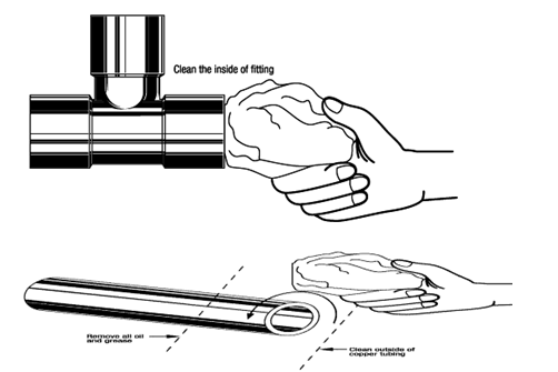
PROPER FLUXING is important because the flux absorbs oxides formed during heating and promotes the flow of filler metal.
To prevent excess flux residue inside refrigeration lines, apply a thin layer of flux to only the male tubing.
Insert the tube into the fitting and, if possible, revolve the fitting once or twice on the tube to ensure uniform coverage.
Insert the fluxed tube end into the fitting.
Maintain support to ensure the proper alignment until the brazing alloy solidifies.
After brazing maintain support for a few seconds (or more) depending upon the size of the joint area.

The assembly is now ready to braze, using brazing alloy manually fed into the joint.
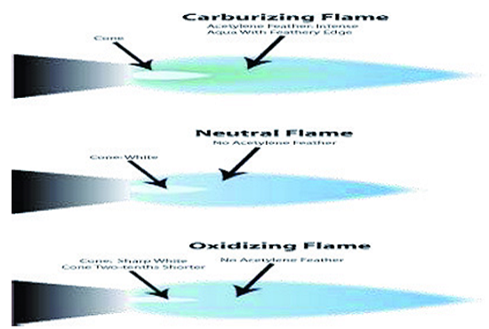
Oxygen / Acetylene Brazing
For most brazing jobs using oxygen-acetylene gases, a carburizing or neutral flame should be used.
The neutral flame has a well-defined inner cone.
Avoid an oxidizing flame.
Excess acetylene removes surface oxides from the copper.
The copper will appear bright rather than having a dull or blackened surface due to an improper oxidizing flame.
Position in accordance with the manufacturer’s instructions.
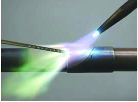
Brazing with air/ acetylene torches is a popular alternative to oxygen mixed fuel gas.
The fuel gas flow aspirates air into a mixer that contains an internal vane that spins the gas to improve combustion and increase flame temperature.
If the tank has a delivery pressure gauge set the delivery pressure at 14-15 psi, if the tank has only contents gauge delivery pressure is pre-set at the factory so open the regulator adjusting screw all the way by turning it clockwise until it “bottoms.”
Open the torch valve.
Opening about 3/4 of a turn will provide sufficient fuel gas delivery.
Do not try to meter pressure, (reducing the flame), by using the torch handle valve.
If a higher or lower flame is required change to a different tip size.
Always keep the torch in short motion.
Start heating the tube, first applying flame at a point just adjacent to the fitting.
Work the flame alternately around the tube and fitting until both reach brazing temperature before applying the brazing filler metal.
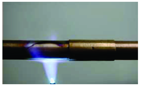
When a flux is used, it will be a good temperature guide.
Continue heating the tube until the flux passes the “bubbling” temperature range and becomes quiet, completely fluid and transparent and has the appearance of clear water.
Direct the flame from the tube to the flange-base of the fitting and heat until the flux that remains in the fitting is also completely fluid.
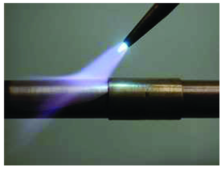
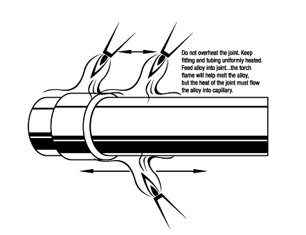
Sweep the flame back and forth along the axis of the assembled joint, tube, and fitting to get and then maintain uniform heat in both parts.
Always keep both the fitting and the tube heated by playing the flame over the tube and the fitting as the brazing alloy is drawn into the joint.
The brazing alloy will diffuse into and completely fill all joint areas.
Do not continue feeding brazing alloy after the joint area is filled.
Excess fillets do not improve the quality or the dependability of the brazing and are a waste of material.
When making vertical alloy-up joints heat the tube first and then apply heat to the fitting.
It is important to bring both pieces up to temperature evenly.
Keep the flame directed toward the fitting.
If the tube is overheated, the brazing alloy may run down the tube rather than into the joint.
When making horizontal joints heat the circumference of the tube first, and then apply heat to the fitting.
Deciding where to start feeding the alloy will depend on the size of the pipe and operator preference.
On large diameter pipe, however, sometimes the best approach is to start at the bottom of the pipe.
As the alloy solidifies, it will create a “dam” and help prevent the brazing alloy from running out of the joint as the remainder of the connection is filled.
When adding alloy, make sure both the pipe and fitting are up to temperature.
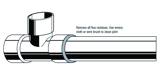
CLEANING OF COPPER AIR CONDITIONING PIPES AFTER BRAZING
All fluxes residues must be removed for inspection and pressure testing.
Immediately after the brazing alloy has set, quench or apply a wet brush or swab to crack and remove the flux residues.
Use emery cloth or a wire brush if necessary.
Be careful with the temperature, the temperature must not be higher than necessary.
Therefore draw the flame back slowly when the melting temperature is reached.
External flux residue must be removed by brushing with hot water.
Do not compress the flare so severely that it becomes hard.
Leave final tightening up until actual installation
Evacuation, flushing and charging Steps
On completing the refrigerant piping installation work, the next steps are:
-
- Evacuation
- refrigerant charging
- Leak testing
Starting up and Adjustment
Remove moisture, atmospheric air and inert gas from the system when evacuating.
The vacuum pump should be capable of quickly bringing the system pressure down to about 0.05 mbar.
Vacuum hoses and tubes must be as short as possible and the diameter sufficiently large.
Normally, an ordinary 1/4″ charging hose not more than 1 m in length can be used.
Evacuate in two stages with refrigerant flushing between.
The process of evacuation, flushing and charging is described below.
Start the pump and allow it to suck the pressure down as far as possible.
Shut off the pump from the rest of the system.
Stop the pump, read off and register the pressure on the vacuum gauge.
Check to ensure that the vacuum can be maintained. If not, replace charging hoses and/or leaking valves and/or vacuum oil in the vacuum pump.
First evacuation
Evacuation from suction side of compressor and possibly also the discharge side.
Charging hose(s) mounted between charging board and compressor.
All valves, incl. solenoid valves, open.
Automatic regulating valves at maximum opening.
Evacuate system, if possible down to the pressure previously indicated by the vacuum gauge.
System vacuum test to be performed again as explained, if any leakage is detected:
Repeat the test until vacuum is maintained or continue with the next point.
Flushing and provisional leak testing
Apply nitrogen pressure to the system (approx. 2 bar over pressure).
Leak-test all connections
If leakage is detected:
-
- Use a recycling unit and vacuum pump to remove nitrogen from the system
- Repair the leakage
- Repeat the process until no system leakage remains.
Second evacuation
If over pressure remains on the system, use the recycling unit to empty it of nitrogen.
-
- Then evacuate again as described under “First evacuation”.
- This will further remove any air and moisture remaining in the system.
- Provisional setting of safety equipment
- Check and set high-pressure control and any other safety equipment, incl. motor protector (setting in accordance with scale values).
After final evacuation, the system can be charged with refrigerant.
A charging board can be used for the purpose and will, with sufficient accuracy, dose the correct quantity of refrigerant for the system.
High accuracy is needed in systems without receiver.
If the system has a charging valve, refrigerant can be supplied in the form of liquid to the liquid line. Otherwise the refrigerant can be supplied as vapour to the compressor suction stop valve with the compressor running.
Charging must be continued until no vapour formation appears in the sight glass – unless vapour formation is due to other faults.
Here however, it is necessary the whole time to check that the condensing pressure and suction pressure remain normal and that the Thermostatic expansion valve superheat is not too low.
Too high a condensing pressure during the charging process can mean that the system has been over-charged with refrigerant and must be partly drained.
Always use the recycling unit if it becomes necessary to drain off refrigerant.
Too little super heating during the charging process can cause liquid hammer in the
Split & Packaged Unit Installation Method Statement Package – Download Editable Files
HVAC EQUIPMENT INSTALLATION
PRE-INSTALLATION CHECK
Upon receipt of the equipment and accessories, carryout material receiving inspection to ensure that the components received are as per specification and purchase order.
Examine for damage and record / inform the responsible authorities if any damage observed.
Offer for quality control inspection and based on the acceptance by all parties release for installation.
After transporting to the project location, choose a dry storage site that is reasonably level and sturdy to prevent undue stress and damage to the unit structure or components.
Do not remove protective caps from piping connections until ready to connect refrigerant piping.
Leave the protected covering as supplied until ready for installation / commissioning activities.
PREPARATION FOR INSTALLATION
Inspect work area for readiness and safety requirements to start the installation work.
All relevant drawings and Manufacturer’s recommendations for the installation shall be available at site for the execution of the job.
Make sure the foundation has necessary clearance to commence unit installation activities.
EQUIPMENT INSTALLATION
Check Unit weight prior to rigging.
Use proper rigging and handling tools while rigging the unit.
Lifting and rigging of the unit shall be in accordance with manufacturer instructions,
Only qualified technicians are allowed to carry out installation of HVAC units.
Ensure cleanliness of the area where the unit is to be installed.
Remove shipping spacers wherever applicable.
Mobilize the unit to the location where to be installed.
Install unit on the foundation as per approved detail drawing and manufacturer recommendations.
Position the unit and align the unit’s foundation so that to match the holes for bolting down/fixing.
Provide vibration dampers / pads underneath the unit to suit the operating weight as required by the manufacturer.
Secure the unit to the foundation with appropriate fasteners.
If required torque-down the fasteners as per manufacturer recommendations.
Ensure adequate clearance for unit service / maintenance access.
Complete the installation of all necessary power and control circuit cabling/glanding and termination in accordance with wiring diagram, P & ID and as per Manufacturer recommendations.
Install refrigeration piping in accordance with P & ID and approved brazing procedure by a qualified brazer.
Ensure shut off valves are fitted on the refrigeration lines to isolate the unit from the piping system during unit servicing (in accordance with the P & ID).
After completing the Leak test / vacuum testing, insulation may be applied.
In the area where applying the insulation is difficult or impossible due to inaccessibility, insulation may be applied over the straight length of piping by leaving joints for later insulation after testing.
Insulate refrigerant pipe in accordance with the scope of work and detail drawing.
The unit base frame shall be fitted with earthing stud located at the base and connect the unit body to the earth boss by use of insulated earth cable (unless otherwise stated different).
Ensure the units / Equipment / instruments / cables etc. are tagged according to the tags assigned in the detail drawing.
INSPECTION AND TESTING
Once the installation is completed, inspect the unit to ensure that the correct installation procedures have been followed.
Inspection and Testing shall be in accordance to the inspection and testing plan ITP and checklists.
Prior to offering for Quality Control inspections, Supervisor shall ensure that all the installations are as per the approved shop drawings.
Ensure that the installed units are free from damages.
Ensure that the pipe connections are as per the approved P & ID / detail drawing and as per Manufactures instructions.
Ensure the maintenance accessibility.
Ensure installation is complete in all respects.
Health Safety and Environmental Requirements
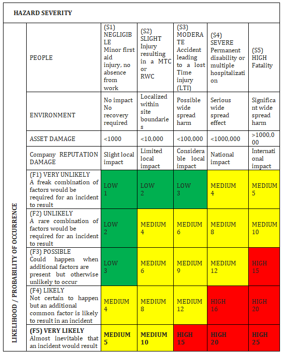
Risks, at each stage are evaluated, utilizing the matrices applicable for the project to determine the level of significance in terms of likelihood of occurrence and severity of hazard based on the allocated numerical values.
LIST OF TYPICAL TASK INVOLVING RISKS
- Hot works
- Bolt Tensioning and Torqueing
- House Keeping (General)
- Pressure test using air.
- Equipment Installations
- Leak Testing
- Manual Handling
- Material handling using forklifts
- Pneumatic Testing
- Portable Electric Hand Tools
- Working at Heights, scaffoldings, ladders
- Working in Fabrication Areas (General)
- Energization of Equipment, Testing & Commissioning
SPECIFIC EMERGENCY PROCEDURES
A Certified First Aider shall be on site at all times whilst a First Aid Clinic shall be available for treatment of light injuries.
In the event of an emergency, all workers shall assemble at an area which shall be allocated by a post sign and wait for further instructions.
This point shall be marked with a sign as “MUSTER POINT” or “Assembly Area“.
The Project Engineer and the HSE officers can assist employees and point them to the assembly point.
Employees shall be made familiar with the locations of “Muster Stations” through Safety Induction and regular Toll Box Meetings.
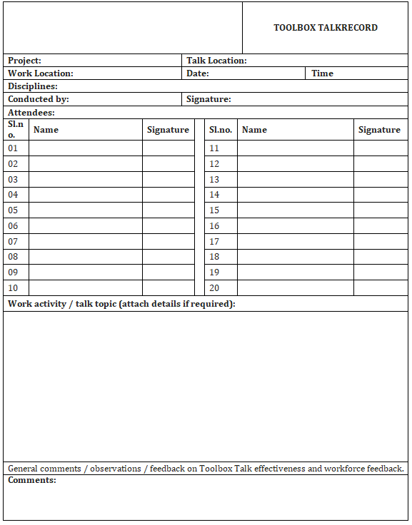
TOOL BOX TALK
Supervisors and foremen shall carry out regular and scheduled toolbox talks.
Subjects for these talks are pre-determined and planned as per Tool Box Talk subjects.
Tool Box talks are also used prior to the commencement of critical activities to reinforce policies and procedures specific to the activity, communicating ‘lessons learnt’ from hazards / incidents and reviewing Job Hazard Analysis.
Safety officer shall conduct toolbox talks for complex activities which require extra precautions.
Attendance at toolbox talks is closely monitored to ensure all employees receive regular and appropriate.
PERSONAL COMMITMENT
- I shall wear my PPE at all times.
- I shall do my best to prevent pollution damage to the environment.
- I shall use the welfare facilities provided for me.
- I shall protect the safety of my fellow workers.
- If I work safely each day, I shall go home each day.
PERSONAL PROTECTIVE EQUIPMENT
Following are the basic personal protective equipment (PPE) those are always used during construction activities to ensure safety of the personnel at construction site:
Protective Clothing: Protective clothing protects the body of the construction staff from hazardous substance.
Helmet: The most important part of the human body is the head. It needs utmost protection which is provided by a hard plastic helmet.
Safety Shoes: Maximum of the working space is occupied with machinery, construction materials which are made of hard metal and which make it clumsy for construction staff to walk around. Safety shoes ensure that nothing happens to the feet while working or walking at site.
Safety Hand gloves: Different types of hand gloves are provided. All these are used in operations wherein it becomes imperative to protect ones hands. Some of the gloves provided are heat resistant gloves to work on hot surface, cotton gloves for normal operation, welding gloves, chemical gloves etc.
Goggles: Eyes are the most sensitive part of the human body and in daily operations chances are very high for having an eye injury. Protective glass or goggles are used for eye protection, whereas welding goggles are used for welding operation which protects the eyes from high intensity spark.
Ear Muff/plug: Noisy construction environment is very high for human ears to bear. Even few minutes of exposure can lead to head ache, irritation and sometimes partial or full hearing loss. An ear muff or ear plug is used during construction activities which dampens the noise to a bearable decibel value.
Safety harness: To avoid a fall from heightened area, safety harness is used. Safety harness is donned by the operator at one end and tied at a strong point on the other end.
Face mask: Working on insulation surface, painting or cleaning involves minor hazardous particles which are harmful for human body if inhaled directly. To avoid this, face mask are provided which acts as shield from hazardous particle.
Split & Packaged Unit Installation Method Statement Package – Download Editable Files
TOOL BOX TALK SHEET
RISK RATING MATRIX
Discover more from Project Management 123
Subscribe to get the latest posts sent to your email.