The following equipment and tools shall be provided with the necessary numbers to suit the numbers of skilled fixers:
- Leveling Instruments
- Masonry Tools
- Brushes
- Rubber Mallets
- Spirit Levels
- Adjustable Wrenches
- Open Wrenches
- Stone Steel Holders
- Spatulas
- Aluminum Straight Edge
- Measurement Tapes
- Stone Cutting Machine/Power Saw
- Plumb Line and Plastic Strings
- Steel Hammers
- Masking Tapes, etc. as required
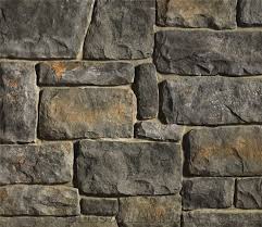
Procedure for Installation Of Stone Cladding Works
All material shall be carefully handled and stored in a way protected from breakage, staining and other damages.
Stone units shall be stored vertically and not in contact with earth surface. Stone cladding shall be properly separated from adjacent units by wood strips or wedges.
Mock-up:
Mock-ups shall be prepared in a size and location as required by the Consultant.
Mock-ups shall be executed for stone color, pattern, aesthetic qualities and workmanship. Approved Mock-ups shall serve as a standard for variation of colors, texture and workmanship.
Mock-ups shall be assembled to stimulate final conditions, indicating all joint/connection & corner details, use of all required accessories, equipment and all other features of final work which is included in scope of Stone Cladding Works.
The sample panel shall retain unaltered throughout the entire period of installation plus one month.
EXECUTION OF STONE CLADDING WORK
Execution of stone cladding works shall be as per details shown on the approved drawings. All cladding shall be attached to the structure of the building by means of anchoring system as specified, in accordance with relevantly approved shop drawings and manufacturer’s recommendations. It shall include all necessary components recommended by manufacturer to rigidly support the cladding in place to the lines and dimensions as shown on the approved drawings. Stone units shall be dense, sound and free from defects that may impair strength or durability of completed works. Mastic compounds shall be used where applicable as approved/recommended by stone manufacturer.
Setting Out & Control of Horizontal and Vertical Lines:
The main starting reference point and level shall be provided by Surveyor following the approved shop drawings. These reference point and levels shall be checked and verified for every location during the progress of Installation.
The setting out of the marble & granite stone cladding work including the Control of Horizontal and Vertical Lines is a joint exercise involving Contractor and the subcontractor work in close co-ordination. The setting out will be controlled through a framework of reference points established on adjacent walls and columns to the location of installation, location and details of which will be included on a Shop Drawing for reference purposes.
A routine inspection and checking shall be established to ensure that the setting out of the Stone cladding work and the fixing of the same is controlled within established parameters with particular attention being given to the Control of Horizontal and Vertical Lines.
Plumb Lines
Plumb lines will be provided for every corner and in other locations where deemed necessary. These lines shall be kept in place during installation and shall be checked regularly. If any deviations from plumb are found due to irregularities in the concrete structure, Surveyor shall establish the main starting reference points and level accordingly.
Installation Procedure (Wall Cladding):
Stone cladding shall be set by mechanics/fitters skilled in the procedure required for the project. Skilled stone fitters shall be employed at site to do necessary field cutting as cladding is set. Power saws shall be used to cut stone as necessary. Exposed edges shall be cut straight and true.
Before commencing of the work in any area, the preparation are due to take place such as:
The surface should be clean and free from any contamination.
The concrete wall is to be straight enough to receive the stone cladding.
Application of damp proof paint / Air Vapor Barrier, (BITUMINOUS PROTECTIVE COATING) should be completed with approved material as per project specifications / shop drawings and manufacturer’s recommendations.
Approved Rock Wool material should be completed as per project specifications / shop drawings and manufacturer’s recommendations.
Stone cladding shall be cleaned thoroughly by scrubbing exposed surfaces with fiber brush followed by thorough drenching with clear water or as recommended by manufacturer.
Stone anchors, supports, fasteners and other attachments shall be installed securely as indicated or required, to secure stone work in place as per detail shown on the approved shop drawing/ manufacturer’s recommendations.
Stone anchors shall be securely drilled in and located as shown on the drawings and shall be set plumb and in true place with the following tolerances.
For Stone cladding adjoining to Aluminum Cladding & glazed curtain wall the procedure of survey and leveling shall be followed before installation on different levels.
Sills, window boards or shelves shall be uniform and homogeneous within each room and cut from a single stone.
Stones shall be laid out for each part to select the material matching to each other.
Sealer shall be applied.
Variation from plumb: For lines and surfaces of columns, walls and arises, stone cladding shall not exceed 6.4mm in 3.05 m, 9.5mm in a story height of max. 6.1m or 12.7mm in 12.2m or above. For external corners, expansion joints and other prominent lines do not exceed by 6.4mm in any story up to a maximum height of 6.1m or 12.7mm in 12.2m or above.
Variation from level: For grades indicated for exposed sills, parapets, horizontal joints and other prominent lines do not exceed 12.7mm in any story up to a maximum height of 6.1m or 19.1mm in 12.2m or above.
Deflection in each cladding panel caused by gravity loads, wind loads and thermal movement, acting singly or in combination with one another, shall be limited to the following maximum:
1.6mm measured in the plane of the wall
1/360 of the panel clear span but not more than 20mm deflection, measured at a perpendicular direction to the wall.
Where cladding is supported on clips or continuous angles, stone shall be set on setting buttons, shims or sheets of resilient to maintain the joint width as indicated on the drawings and as per manufacturer’s recommendation. Settings buttons shall be placed of adequate size, in sufficient quantity and of same thickness as of indicated joint width, to maintain uniform joints in accordance with approved drawings and manufacturer’s recommendations.
Cavities shall be kept open and will not be filled with mortar or grout where unfilled space is indicated between back of stone cladding and face of substrate wall following the approved drawings/ project specs/ manufacturer’s recommendations.
Joint sealant and backer rods shall be installed where shown on the drawings in accordance with the printed directions of the sealant manufacturer as approved.
Joints up to 900 mm from FFL at external face shall be grouted and above from this level remained open as detailed in shop drawings/specifications.
All works in progress shall be protected during construction by a suitable impervious film or fabric securely held in place or as recommended by manufacturer.
Installation of Structural Steel for Stone Cladding
A prefabricated steel structure will be installed at elevation, to support and fix the external stone cladding. The fixation of this steel structure will be as per approved shop drawing.
Cleaning and Patch up
Each completed area will be thoroughly cleaned free of any bonding material, traces of dirt & mortar stains and other defacement from stone work. Stone units that require repairing or patching shall be removed, repaired or replaced as per Consultant advice.
Discover more from Project Management 123
Subscribe to get the latest posts sent to your email.